Monitoring system for monitoring processing equipment

a monitoring system and processing equipment technology, applied in the direction of programme control, cleaning process and apparatus, automatic controllers, etc., can solve the problem of difficult to quickly determine the location of a fault in the production lin

Inactive Publication Date: 2003-03-18
SONY ELECTRONICS (SINGAPORE) PTE LTD
View PDF23 Cites 73 Cited by
  • Summary
  • Abstract
  • Description
  • Claims
  • Application Information

AI Technical Summary

Problems solved by technology

Therefore, in view of the large number of individual steps which are required during assembly, ...

Method used


Image

  • Monitoring system for monitoring processing equipment
  • Monitoring system for monitoring processing equipment
  • Monitoring system for monitoring processing equipment

Examples


Embodiment Construction

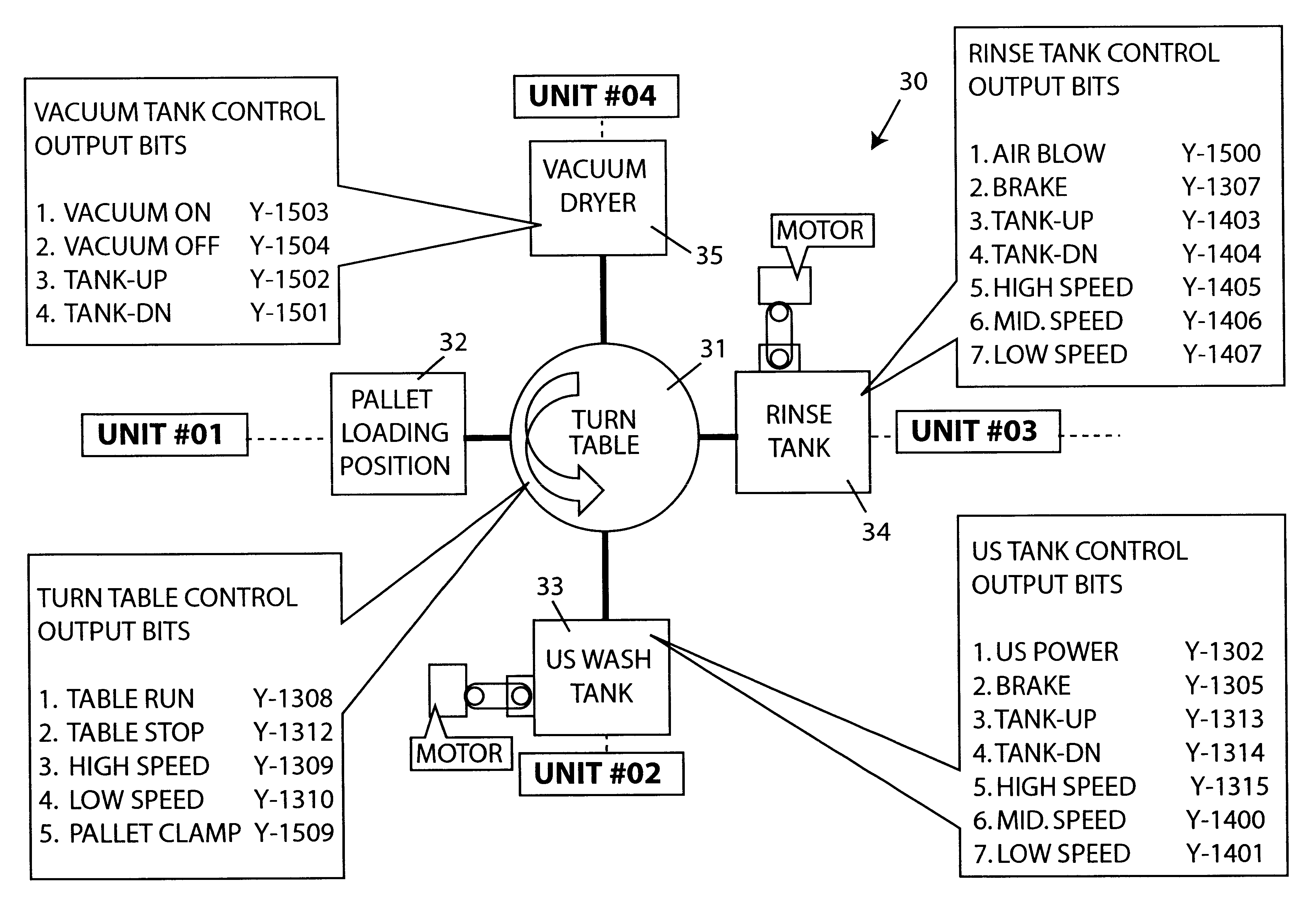
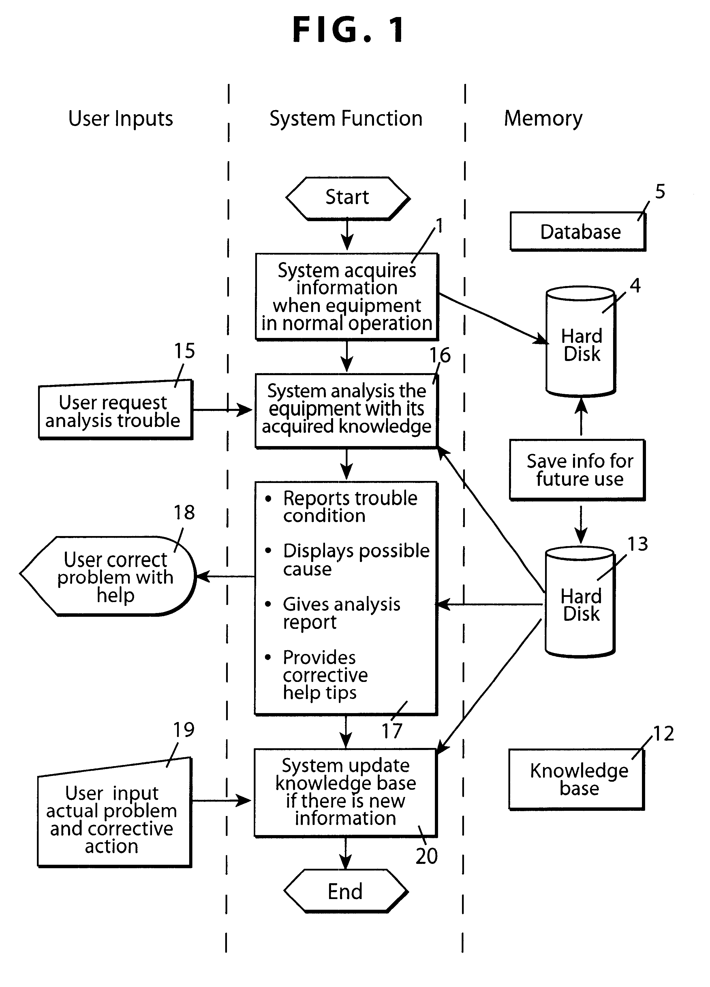
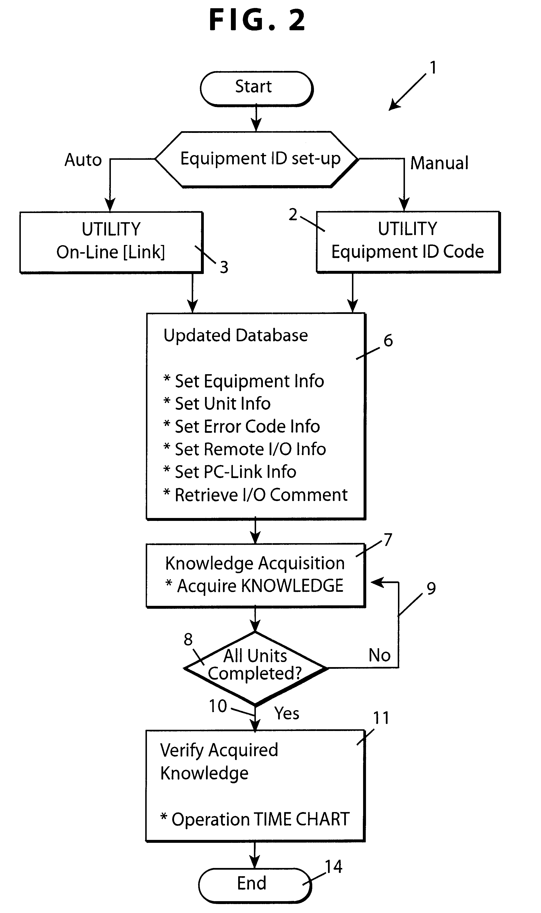
FIG. 1 is a schematic block diagram illustrating a monitoring system for monitoring processing equipment, such as an automated production line, for faults, trouble or any other abnormality which may occur in the processing equipment. As shown in FIG. 1, initialisation of the system involves the system acquiring reference data from the processing equipment when the processing equipment is in normal operation (step 1). The process of acquiring the reference data (step 1) is shown in more detail in FIG. 2.

As shown in FIG. 2, the system acquires the reference information (step 1) by initially reading in the ID code of the process equipment either by an operator entering this information manually (step 2) or automatically (step 3) by an on-line link to the processing equipment. After the processing equipment ID code has been obtained, a database 5 held on a hard disk 4 of a computer is updated (step 6) with information concerning the processing equipment. In particular, the number and de...


PUM


Abstract

A monitoring system for monitoring processing equipment includes a controller which emits control signals to control the processing equipment. A computer is coupled to the controller. The computer records the control signals emitted by the controller and records status signals received from sensors mounted on the processing equipment. The computer represents the processing equipment as a number of individual cyclical units. Each cyclical unit has an identical sequence of operations during every cycle. The computer also records, for each cycle of every unit, information corresponding to whether the unit has started and completed the cycle.

Description

The invention relates to a monitoring system for monitoring processing equipment and in particular, to permit diagnosis of abnormalities in the processing equipment.BACKGROUND TO THE INVENTIONAutomated production lines are now common for manufacturing a large number of articles where there are a number of repetitive steps which must be carried out on each article during production. Generally, an automated production line has a number of different stations and each station performs a predetermined operation in the manufacture or assembly of the article concerned.Such automated production lines are now common place in the electronics and automotive industries.For example, automated production lines are used for the assembly of cathode ray tubes (CRTs) for use in visual display units (VDUs) and televisions. Such a production line takes all the individual components and assembles them to form the finished CRT and then typically subjects the CRT to testing to ensure that the finished CRT...

Claims


Application Information

Patent Timeline
IPC IPC(8): G05B23/02G05B19/418G05B19/05B08B3/12G05B19/18G05B19/4063
CPCG05B19/058G05B23/024G05B19/4184G05B2219/23237Y02P90/02
Inventor KONAR, PERIYATHIRUVADI GURUNATHAN
Owner SONY ELECTRONICS (SINGAPORE) PTE LTD
Why Eureka
Try Eureka