Application of one or more reagents to a test strip substrate is a highly difficult task.
There are several major limitations associated with using a conventional
solenoid valve, such as the Lee valve, as a drop-on-demand valve in a
reagent dispensing
system.
Such a tortuous fluid path results in significant disadvantages, such as localized pressure drops which undesirably lead to bubble
precipitation of air or gas in solution.
The
entrapment of these bubbles in the fluid path can not only degrade the quality of the reagent or liquid dispensed but can also render the dispenser susceptible to clogging.
Thus conventional dispensing valves require frequent purges of the fluid into a waste receptacle, thereby, disadvantageously, reducing
process efficiency and increasing wasteful consumption of reagent.
Moreover, the air or gas bubbles affect the
compressibility of the fluid which can complicate the operational dynamics of the dispense and aspirate / dispense functions.
While some of these bubble generation problems can be controlled or mitigated by adding surfactants or various other chemical additives to modify the
surface tension and / or other fluid and flow characteristics of the reagent, compatible
chemistry is not available for all reagents.
Also the use of surfactants and other chemicals can often lead to other problems in the dispensing apparatus, and its operation and application.
Thus, there is a major reliability problem with many conventional
solenoid valve dispensers that needs to be addressed.
Since the energizing of the solenoid coil can generate significant heat, the nearby fluid can experience substantial temperature rises.
These temperature changes can further accentuate the bubble generation problem, and also lead to fluid degradation.
Additionally, the tortuous fluid path through conventional solenoid valves causes fluid mixing and
entrapment of dead volumes of fluid.
Undesirably, this fluid mixing and entrapment can lead to fluid degradation,
contamination and
dilution problems in dispense and aspirate / dispense operations, thereby, requiring additional fluid movements through the valve to flush out degraded fluid and / or contaminants.
Also, the unibody construction of typical
actuator and valve elements limits the adaptability of the dispense
system because the
actuator is permanently incorporated with a particularly configured valve element and can only be used with that particularly configured valve element.
Undesirably, this unibody construction complicates repair, maintenance and replacement of the valve and, hence, undesirably adds to the cost of the
system.
Another problem associated with conventional solenoid valves is that many of the different materials that they are fabricated from are exposed to fluid and may be susceptible to
chemical attack by some solvents.
Disadvantageously, this can not only cause valve malfunction but can also lead to fluid
contamination.
But, it is difficult using conventional construction methods to fabricate a typical solenoid dispenser having a
diameter less than about 7 to 8 mm.
In such situations valve costs per line can be very high which can preclude their use in high-density applications.
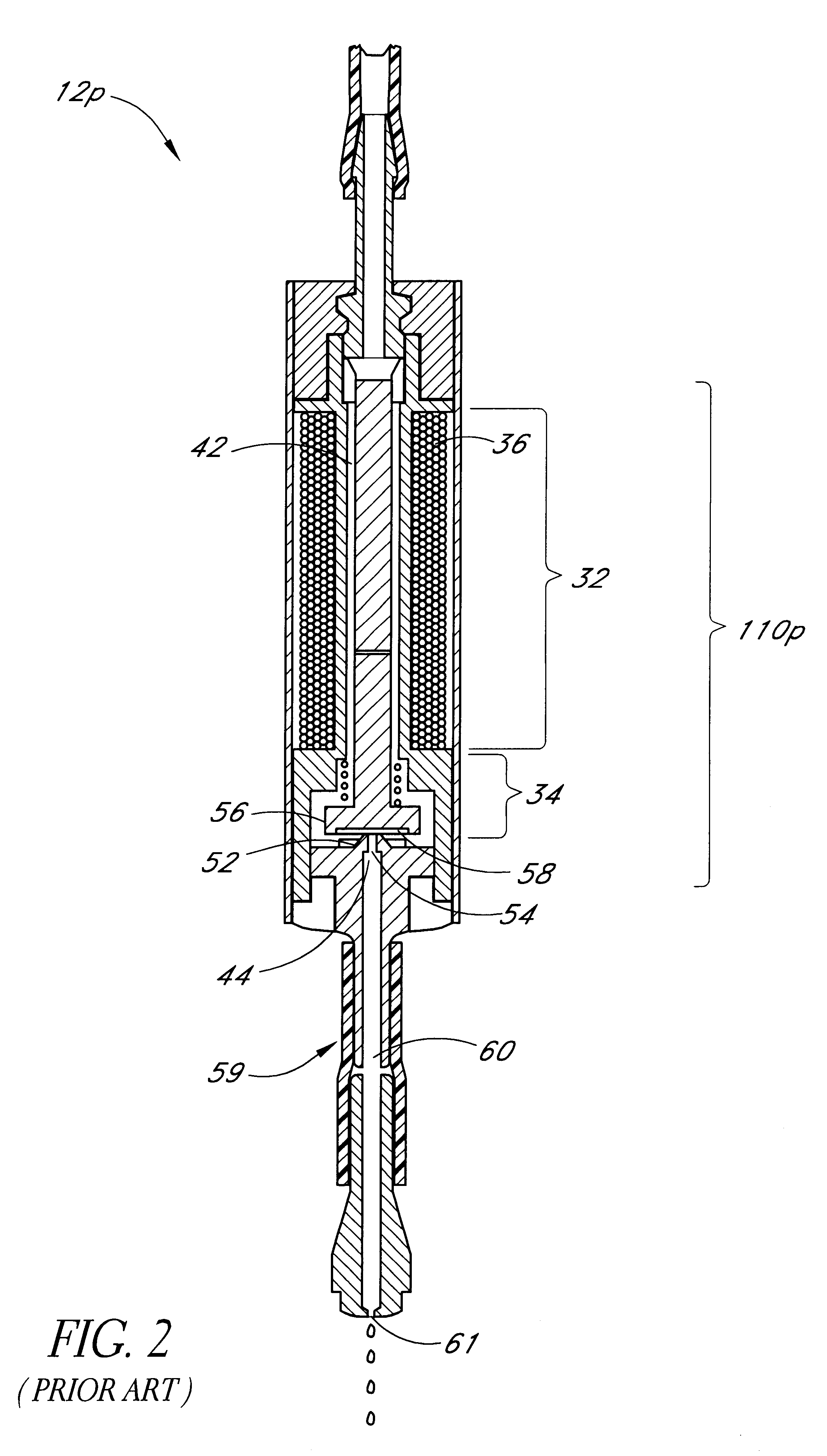
This constraint on the use of the dispenser 12p and the valve 110p also complicates repair, replacement of the dispenser 12p and the valve 110p, thereby undesirably adding to the cost of the system.
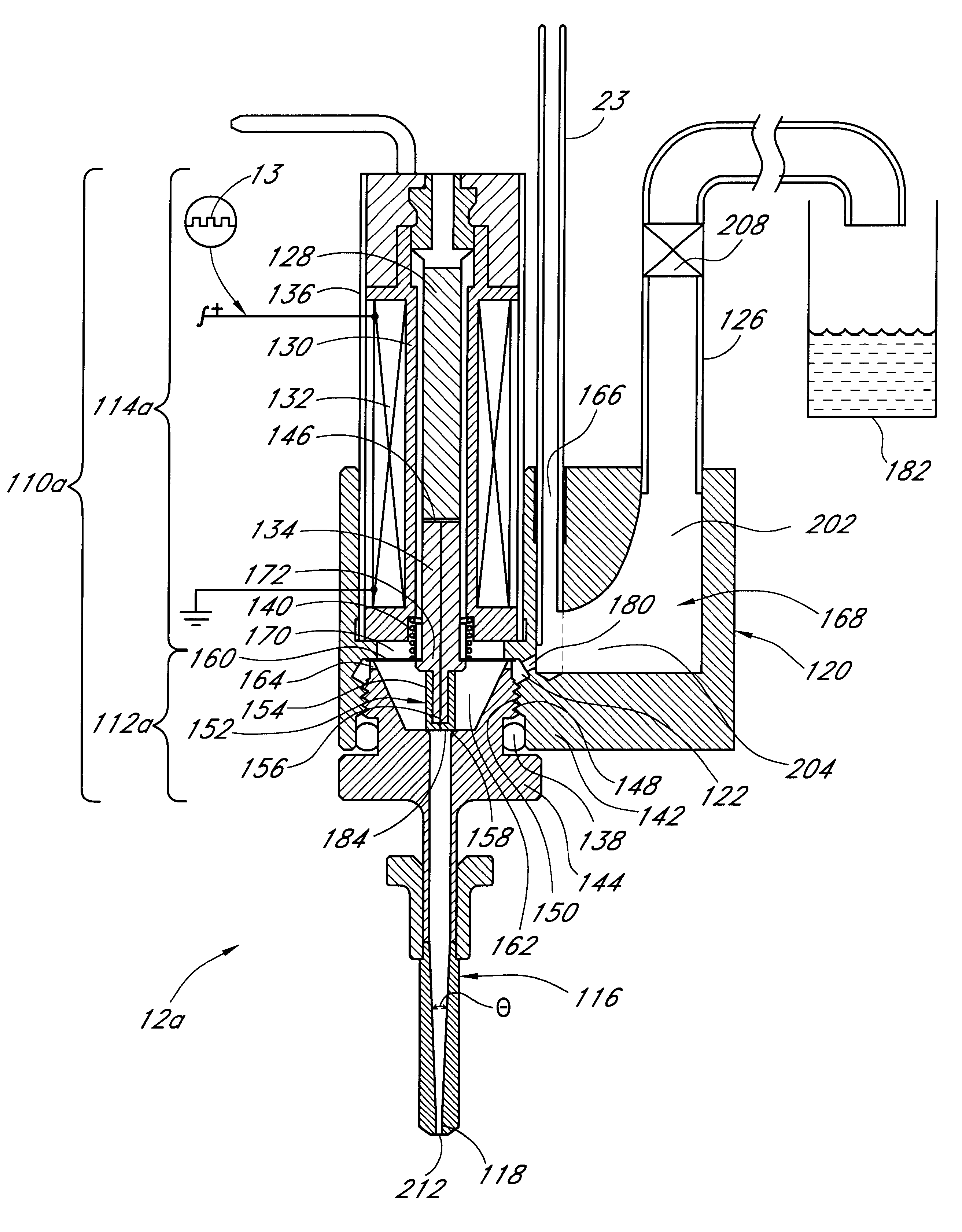
This undesirable temperature rise not only degrades the fluid quality and can adversely affect the quality of the end-result of the dispensing operation, but also accentuates the formation of air / gas bubbles in solution from dissolved air / gas in the reagent or liquid to be dispensed.
These bubbles can accumulate in the valve portion 34 and result in clogging of the dispenser 12p.
Buoyancy forces may also cause the bubbles to rise and collect in the annular passage, thereby further accentuating the clogging problem.
The collection of air / gas bubbles within the valve 110p also affects the bulk
compressibility of the reagent or liquid and this can complicate the operational dynamics of the dispense and aspirate / dispense functions, particularly at high frequencies, thereby potentially resulting in unpredictable and unreliable dispenser performance.
Undesirably this can lead to fluid degradation,
contamination and
dilution problems in dispense and aspirate / dispense operations requiring fluid movement through the valve 110p.
Of course, frequent clogging will require frequent purges, thereby, disadvantageously, reducing
process efficiency and increasing wasteful consumption of reagent or liquid.
This problem can be particularly severe during aspiration.
For example, if a purge has to be performed after a substantially large volume of fluid has been aspirated and which is mostly still resident within the dispensing apparatus, then performing a purge not only wastes the aspirated fluid but also requires the aspirate operation to be repeated to recover the lost fluid.
In addition, the tapering of the tip lower portion 196 does not provide sharp corners or edges which prevents bubble accumulation in the tip 116.
In contrast, and as discussed above for such a situation, for a conventional prior art dispenser 12p (see FIG. 2) a purge operation needs to be performed, to relieve clogging due to bubble collection in the annular passage 42, that disadvantageously not only requires repositioning of the dispenser 12p and wastage of source fluid, but also the possible need to repeat the aspirate operation, all of which adds to the cost by reducing
process efficiency.

