Latch chain having improved sensitivity

a technology of latch chain and sensitivity, which is applied in the direction of pulse generator, pulse technique, electrical apparatus, etc., can solve the problems of latch sensitivity to input voltage performance limitations, and achieve the effects of improving sensitivity, reducing output voltage swing, and improving input voltage sensitivity

Inactive Publication Date: 2003-03-25
LUCENT TECH INC +1
View PDF3 Cites 32 Cited by
  • Summary
  • Abstract
  • Description
  • Claims
  • Application Information

AI Technical Summary

Benefits of technology

One aspect of the present invention is directed to a latch chain having improved input voltage sensitivity. The chain includes a first latch, an amplifier, and a second latch connected in series. The second latch is a conventional latch. The first latch is modified to have a higher sensitivity and lower output voltage swing than conventional latches. The modified latch includes a pair of matched output transistors that generate output voltages and a pair of matched biasing circuits to

Problems solved by technology

The sensitivity of a latch to input voltages sets performance limitations

Method used


Image

  • Latch chain having improved sensitivity
  • Latch chain having improved sensitivity
  • Latch chain having improved sensitivity

Examples


Embodiment Construction

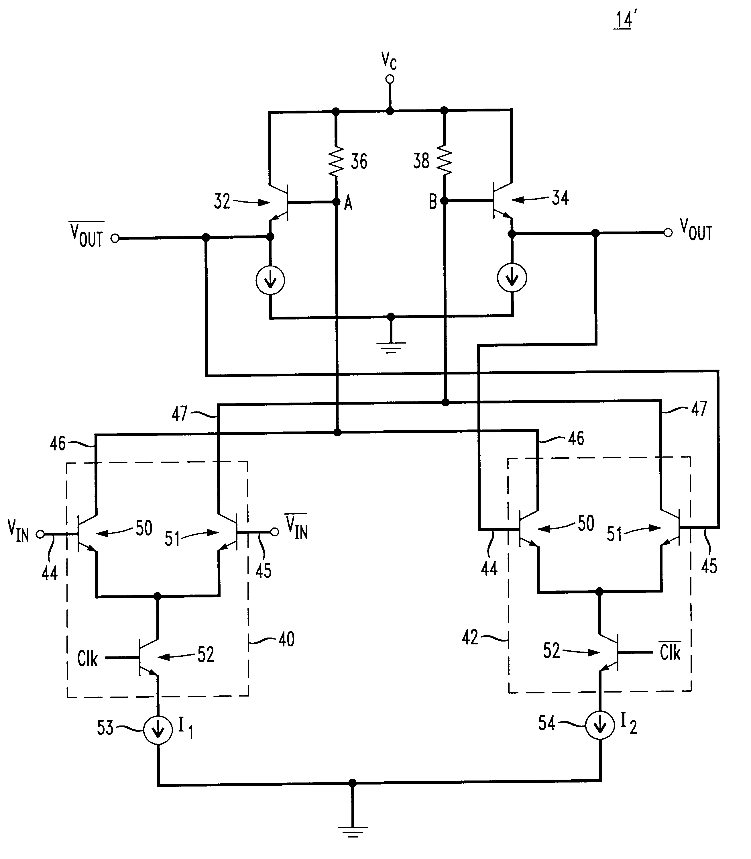
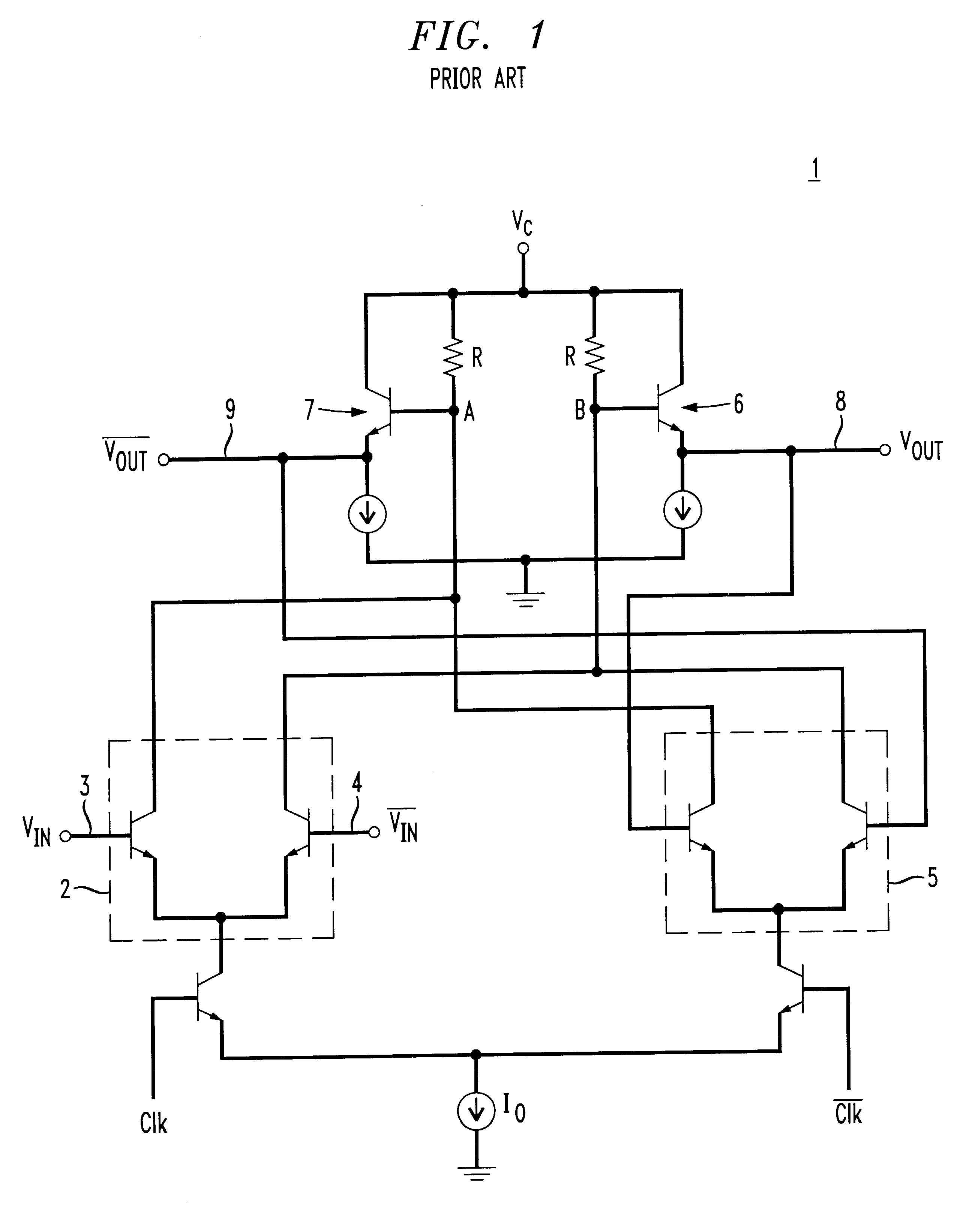
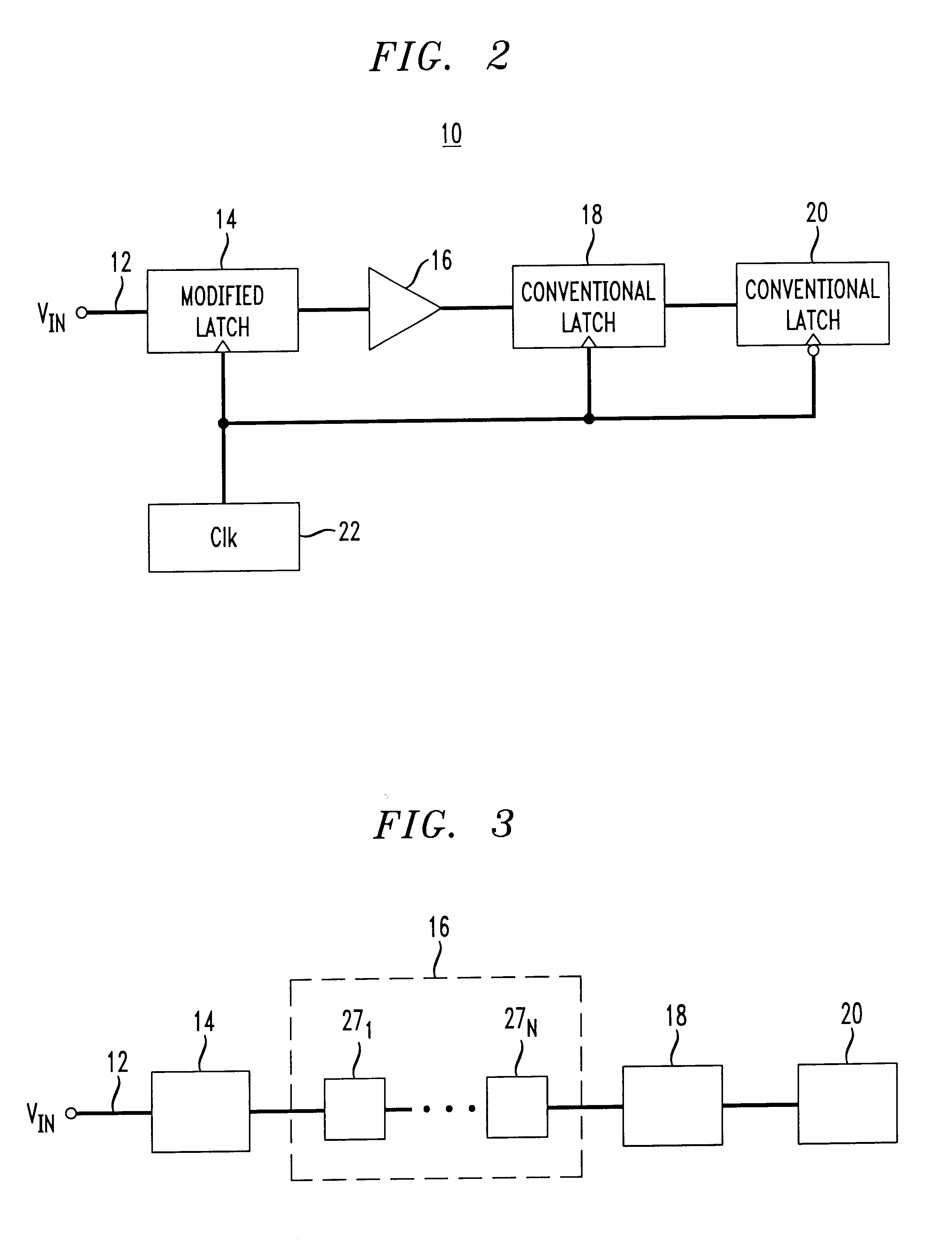
FIG. 2 is an exemplary latch chain 10 with improved sensitivity to input voltages Vin. Latch chain 10 includes a modified latch 14, an amplifier 16, and conventional latches 18, 20, which are serially connected to the output of the amplifier 16. Two conventional latches 18, 20 are shown in FIG. 2, however, any number of one or more conventional latches may be serially connected in the chain, as desired. Each latch 14, 18, 20 has a sample period and a hold period triggered by signals from an external clock 22. The amplifier 16 is not controlled by the clock 22.

Modified latch 14 has an input terminal 12 that also serves as the input terminal for the latch chain 10. At its input terminal 12, the modified latch 14 has a higher input voltage sensitivity than conventional latches 18, 20 of the chain 10. As a result of the higher input voltage sensitivity of modified latch 14, the entire latch chain 10 is more sensitive to input voltage Vin swings.

Referring again to FIG. 1, prior to storin...


PUM


Abstract

A latch chain having improved input voltage sensitivity. The chain includes a first latch, an amplifier, and a second latch connected in series. The second latch is a conventional latch. The first latch is modified to have a higher sensitivity and lower output voltage swing than conventional latches. The modified latch includes a pair of matched output transistors that generate output voltages and a pair of matched biasing circuits to bias the bases of the output transistors with bias voltages. A sample stage is connected so as to apply first biasing currents to one of the biasing circuits in response to input voltages applied to the first latch during the sample period. In addition, a hold stage is connected so as to apply second biasing currents to the biasing circuits during a hold period. The sample and hold stages are configured to apply different voltage differences between the bases of the output transistors.

Description

The present invention relates to digital latches and latch chains having improved sensitivity.DESCRIPTION OF RELATED ARTFIG. 1 shows a conventional digital latch 1 that includes a sample stage 2 with complementary voltage inputs 3, 4, a hold stage 5, and matched transistors 6, 7 having complementary voltage outputs 8, 9. The transistors 6,7 are biased by complementary currents through matched resistors R.During a sample period, sample stage 2 generates a current through resistors R to produce a voltage difference Vab between nodes A and B responsive to the voltage difference Vin-Vin between input terminals 3 and 4. The values of the voltage difference Vab correspond logical values +1 and 0. During a subsequent hold period, hold stage 5 maintains the current through resistors R so that the voltage difference Vab remains unchanged. The voltages at nodes A and B cause output voltages Vout and Vout at output terminals 8 and 9, respectively. The difference between output voltages Vout an...

Claims


Application Information

Patent Timeline
IPC IPC(8): H03K3/00H03K3/012H03K3/2885H03K3/287
CPCH03K3/012H03K3/2885H03K3/287
Inventor CHEN, YOUNG-KAIDORSCHKY, CLAUSGROEPPER, CARSTENGEORGIOU, GEORGEMATTIA, JOHNPULLELA, RAJASEKHARREINHOLD, MARIO
Owner LUCENT TECH INC
Why Eureka
Try Eureka