Dynamic data storage control method and system

a data storage and control method technology, applied in the field of data storage control methods and systems, can solve problems such as inability to record all desired image data successfully, premature end of image recording, and sometimes full recording mediums

Inactive Publication Date: 2003-03-25
SANYO ELECTRIC CO LTD
View PDF8 Cites 70 Cited by
  • Summary
  • Abstract
  • Description
  • Claims
  • Application Information

AI Technical Summary

Benefits of technology

This configuration is preferable for a case in which the external recording medium is removed before judgment is made not to store data on it, for example, when it becomes 50% full. In such a case, this configuration allows the user to continue recording while exchanging the external recording medium. Simply installing a new external recording medium moves data from the internal storage means to the installed external medium, thereby allowing data to be recorded seamlessly across medium exchange.
For example, when image data is coded into variable length data, the amount of code generated in a short period of time is variable. This means that the amount of image data (for example, the number of pictures of image data or the recording time of moving image data) is variable. In such a case, the system according to the present invention prevents a situation in which a desired image data is not recorded just because the amount of data cannot be predicted precisely in advance. Therefore, the present invention is applicable to a data storage system which contains a variable amount of data, for example, an image recording system which codes data into variable length data.

Problems solved by technology

Therefore, the recording medium sometimes becomes full before all the image data is recorded, in which case image recording is ended prematurely.
This means that, if an image recording system user does not know a recording time, he or she has sometimes image recording interrupted and therefore cannot record all desired image data successfully.
No efficient method has been developed for predicting how long a user may continue recording on a current medium.
A disadvantage to this solution is that a less amount of code degrades the quality of decoded image data.
The problem also applies when other types of data, such as voice data, are recorded on an external storage medium.

Method used


Image

  • Dynamic data storage control method and system
  • Dynamic data storage control method and system
  • Dynamic data storage control method and system

Examples


embodiment 1

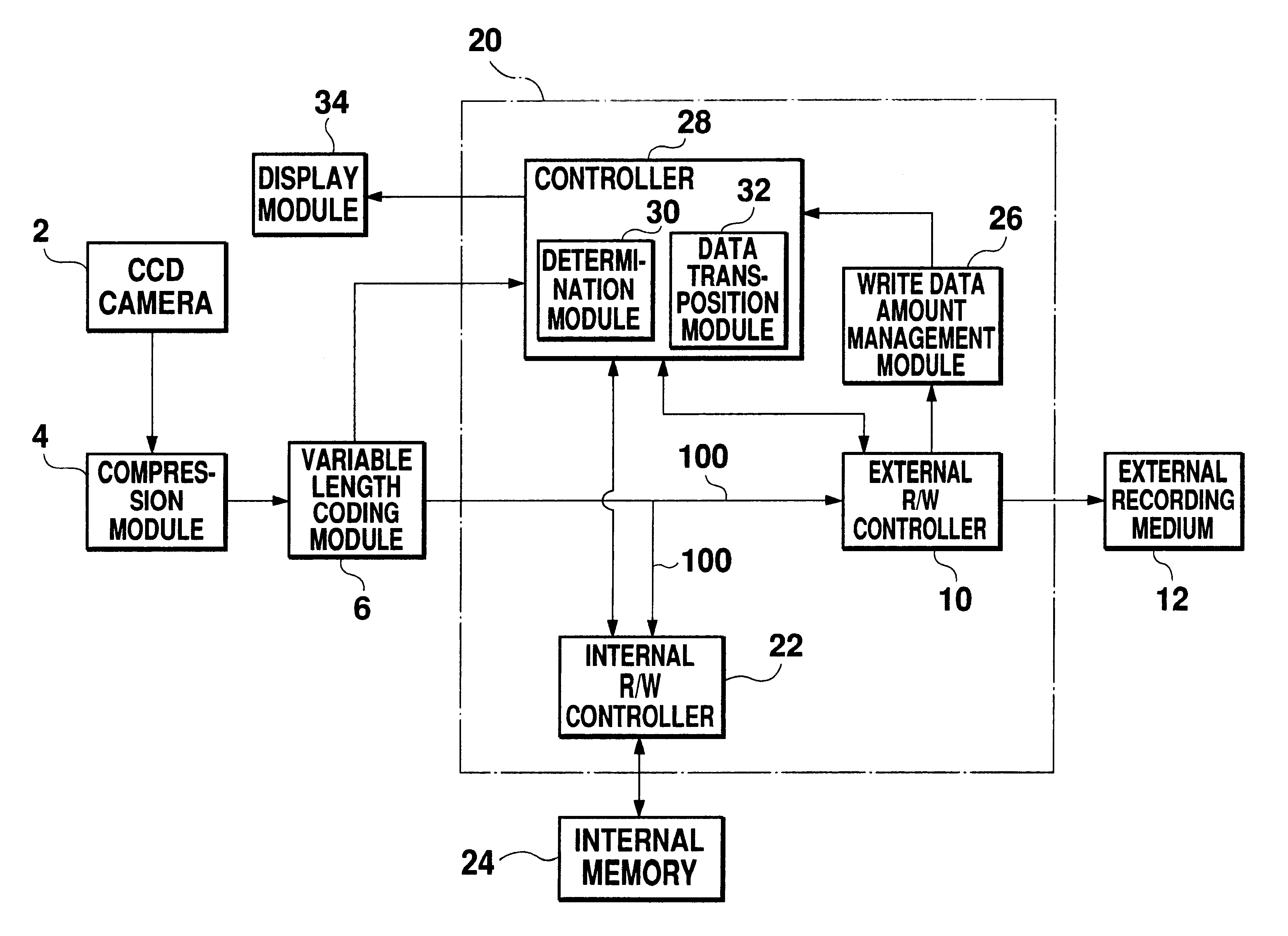
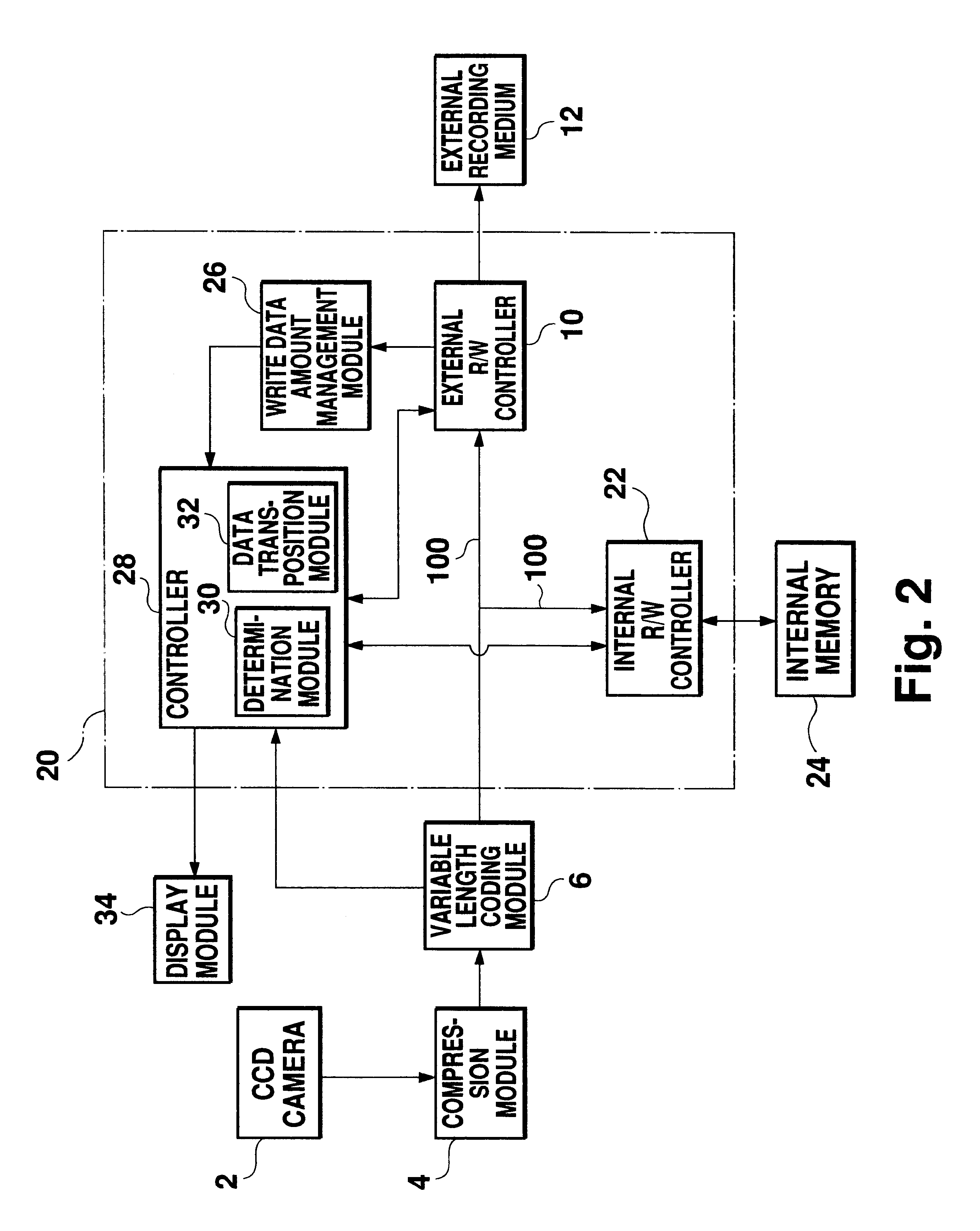
FIG. 2 shows the configuration of an image recording system with an image recording controller 20. The same numbers are used for components in FIG. 2 corresponding to those in FIG. 1. The following description focuses on differences between these components and those described and shown in FIG. 1.

In addition to an external R / W controller 10, the image recording controller 20 has an internal memory read / write controller 22 (hereafter called an internal R / W controller). Coded data 100 generated by a variable length coding module 6 is sent to the external R / W controller 10 and to the internal R / W controller 22. The internal R / W controller 22 controls the writing and reading of coded data to or from an internal memory 24 contained in the image recording system. This internal memory 24 functions as an image data temporary buffer when the external recording medium 12 becomes full. The size of the internal memory 24 may be set according to the system size; for example, the internal memory ...

embodiment 2

The configuration of this embodiment is similar to that of the first embodiment shown in FIG. 2. However, in this embodiment, the determination module 30 controls the internal R / W controller 22 in a different manner from that of the first embodiment. In this embodiment, the determination module 30 compares the amount of free space on the external recording medium, received from the write data amount management module 26, with the amount of picture code received from the variable length coding module 6. Based on the comparison result, the determination module 30 sends the control signal to the internal R / W controller 22 as follows:

(1) When the amount of coded picture data to be recorded next is less than the amount of free space on the medium (usual recording time):

The determination module 30 outputs the "update signal" to the internal R / W controller 22. In response to this signal, the internal R / W controller 22 writes sequentially-entered coded data into the internal memory 24. When...

embodiment 3

Unlike the write operation in the first and second embodiments, coded data is written first in the internal memory and then on the external medium in this embodiment. Data in the internal memory is overwritten by sequentially-entered new data. Coded data is sent from the internal memory to the external recording media on an FIFO basis.

FIG. 6 shows the configuration of an image recording system with an image recording control system 40 of this embodiment. The same numbers are used for components in this figure corresponding to those in FIG. 2. The following describes mainly the differences of components from those in FIG. 2.

In this embodiment, the variable length coding module 6 outputs coded data only to an internal R / W controller 42. The internal R / W controller 42 writes received coded data into an internal memory 44. From the internal memory 44, coded data is sent to an external R / W controller 46 on an FIFO basis. The external R / W controller 46 writes received coded data to the ex...


PUM

PropertyMeasurementUnit
lengthaaaaaaaaaa
space frequencyaaaaaaaaaa
variable lengthaaaaaaaaaa

Abstract

Image data coded by a variable length coding module is output to an external R / W controller and an internal R / W controller. A determination module compares the amount of coded picture data to be recorded next with the amount of free space on an external recording medium. If there is enough free space, image data is written on the external recording medium. If free space is insufficient, subsequent image data is written into an internal memory. When image data is coded into variable length data, it is difficult to predict precisely a recording time of the external recording medium, which means that the external recording medium may become full before a desired amount of image data is recorded. However, image recording may be continued using the internal memory even after the external recording medium becomes full.

Description

1. Field of the InventionThe present invention relates to a data storage control method and system, and more particularly to a method and a system which controls writing of image data to a storage medium. The present invention also relates to a data storage system with the above control function.2. Description of the Related ArtTechnology for compressing and coding moving image data and storing it on various types of storage media is evolving. One of typical technology is MPEG. Today, many manufacturers are developing multimedia units and trying to market MPEG-conforming products.FIG. 1 shows an outline configuration of an MPEG-conforming image recording system with a CCD camera 2. This image recording system has a compression module 4, a variable length coding module 6, and an image recording control system 8. The compression module 4 performs Discrete Cosine Transformation (hereafter called DCT) on video input data and then quantizes the transformed data. The compression module 4 ...

Claims


Application Information

Patent Timeline
Patent Type & Authority Patents(United States)
IPC IPC(8): H04N5/77H04N5/926G11C7/00G11B20/10H04N5/765H04N5/781
CPCH04N5/772H04N5/77H04N5/9264G11B20/10037G11B2220/652
Inventor NIWA, MAYUMI
Owner SANYO ELECTRIC CO LTD
Why Eureka
Try Eureka