Integrated isolator fused coupler method and apparatus

a technology of fused coupler and isolator, which is applied in the direction of optics, instruments, optical light guides, etc., can solve the problems of affecting the overall loss of the optical system

Inactive Publication Date: 2003-04-08
II VI DELAWARE INC
View PDF19 Cites 24 Cited by
  • Summary
  • Abstract
  • Description
  • Claims
  • Application Information

AI Technical Summary

Problems solved by technology

Optical isolators have been used to allow light to propagate only in one direction, the light propagating in the other direction will be directed into a different optical path and suffers a significant loss in such prior devices.
This type of integration is usually bulky and not cost effective.
In addition, a splice causes loss, which adds to the overall loss of the optical system.
However, such prior art taps suffer from a number of shortcomings.
A temperature insensitive filter is thus required in most applications, which adds cost.
Further, the tapping is not provided directly on the output of the device or on the input of the device.
The variation of optical coupling of tap port and output port will create variations in the tap ratio with respect to environmental changes which is not desirable in the optical systems.
In addition, such prior art taps also suffer from various other shortcomings.
However, it is known that the optical characteristics of such coatings have a tendency to change with temperature as well and this may adversely affect the tap performance.
As one can appreciate, and as is well known in the prior art, precise alignment of prior art taps is difficult at best.
Failure to properly align the tap or mechanical shock, e.g., from dropping the unit, will result in additional unwanted optical losses.
However, the addition of an HBS to the tap circuit creates its own problems and complications, not the least of which is cost.
The HLBS is usually costly and lossy.
Manufacturing of this type of device is non-trival and it suffers the same problem of variation of tap ratio with respect to environmental changes as explained in the case of dialectic thin film tap-isolators.

Method used


Image

  • Integrated isolator fused coupler method and apparatus
  • Integrated isolator fused coupler method and apparatus
  • Integrated isolator fused coupler method and apparatus

Examples


first embodiment

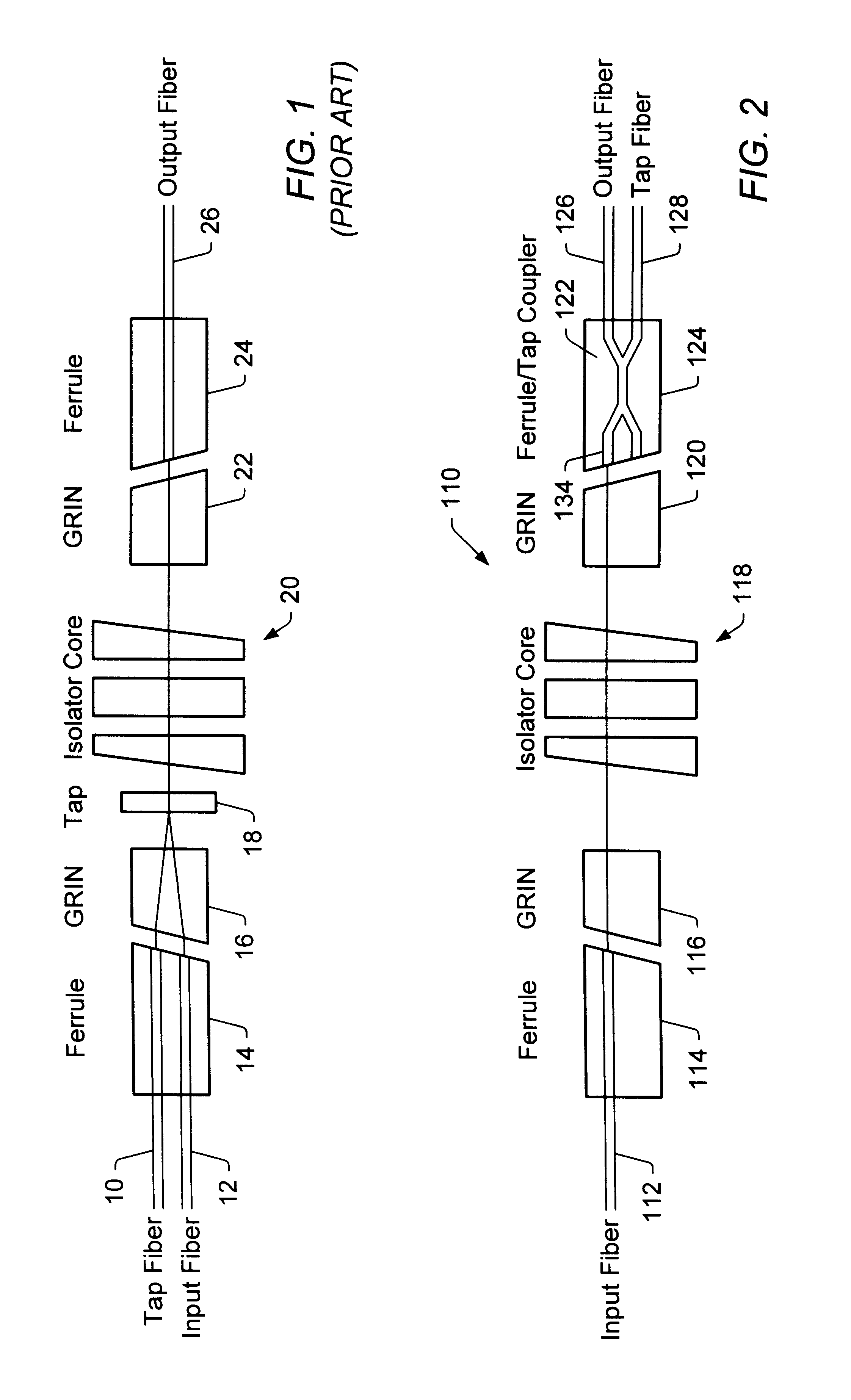
Referring now to FIG. 2, reference numeral 110 is directed to an integrated isolator fused tap coupler according to the present invention. Integrated fused tap coupler 110 includes an input fiber 112 affixed within ferrule 114 which, in turn, is optically coupled to GRIN lens 116. GRIN lens 116 is thereafter optically coupled to isolator 118. By further providing an 8.degree. to 12.degree. angle at the ferrule / coupler interface, back-reflection may be precluded as well. This will be true as well for the additional applications disclosed below for similar ferrule / coupler junction regions.

As will be appreciated by those individuals having skill in the art, GRIN lens 116 is appropriately formed to collimate light signals entering GRIN lens 116 in the direction of isolator 118. Likewise, as will be appreciated by those individuals having skill in the art, isolator 118 is appropriately formed to allow light to pass only in one direction through isolator 118; and in this case, when viewin...

second embodiment

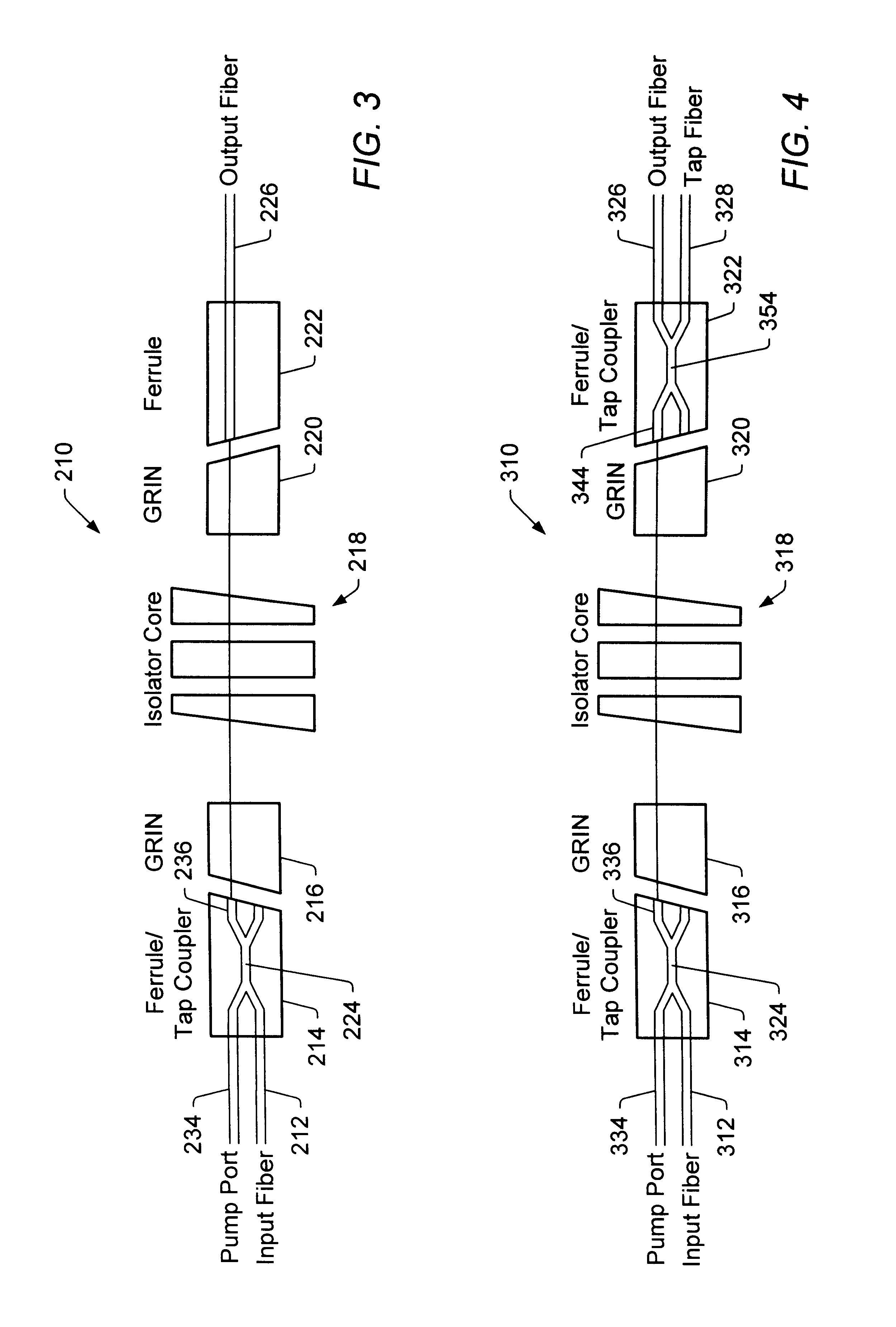
Referring now to FIG. 3, reference numeral 210 is directed to an integrated isolator fused WDM according to the present invention. Integrated isolator fused WDM 210 includes WDM 224 within ferrule 214 at a first operative end of WDM-isolator 210. WDM 224 includes an input signal fiber 212 and a pump port 234 on one side of WDM 224 and an output port 236 on the opposing side of WDM 224. Output port 236 is thereafter optically coupled to GRIN lens 216. GRIN lens 216 is then optically coupled to isolator 218 which in turn is optically coupled to a complimentarily, but reversedly, arranged GRIN lens 220 (as compared to GRIN lens 216). Likewise, GRIN lens 220 is optically coupled via ferrule 222 to output fiber 226. Furthermore the entirety of the disclosed FIG. 3 device is encapsulated within an appropriate housing (not shown) forming an integrated WDM / isolator unit.

As will be understood by those individuals skilled in the art, a fiber optic pumping / amplifying circuit is one in which a ...

third embodiment

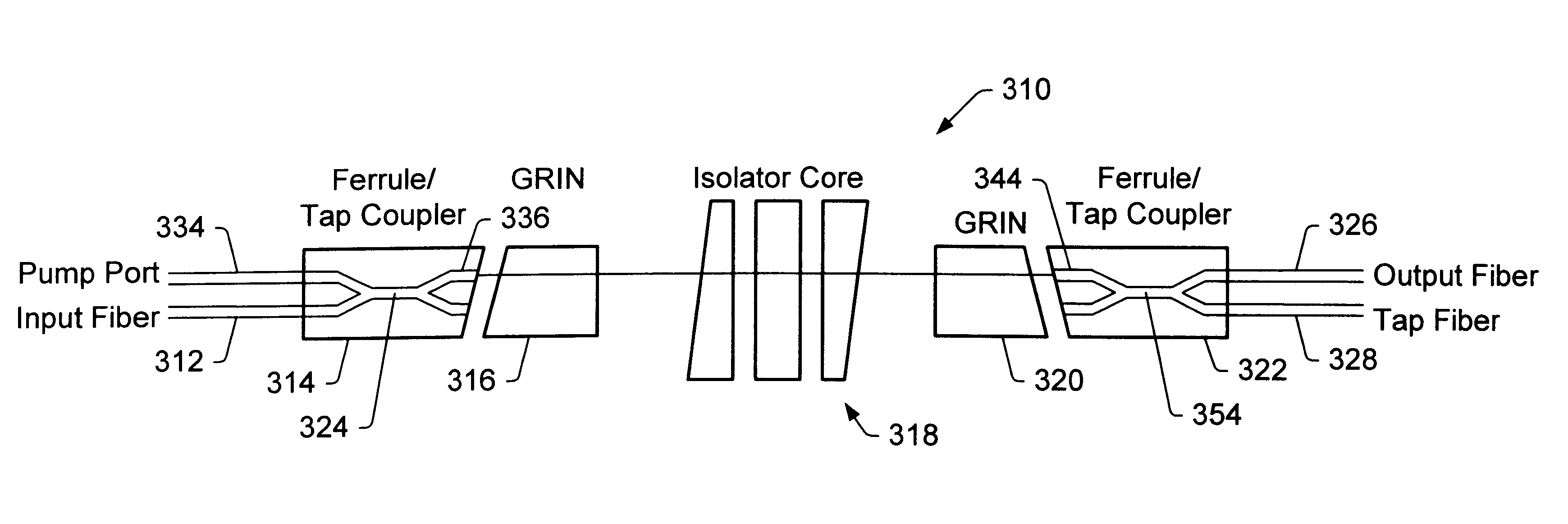
Referring now to FIG. 4, reference numeral 310 is directed to an integrated isolator WDM tap coupler according to the present invention. Integrated isolator fused WDM tap device 310 includes WDM 324 within ferrule 314 at a first operative end of device 310. WDM 324 includes an input signal fiber 312 and a pump port 334 on one side of WDM 324 and an output port 336 on the opposing side of WDM 324. Output port 336 is thereafter optically coupled to GRIN lens 316. GRIN lens 316 is then optically coupled to isolator 318 which in turn is optically coupled to a complimentarily, but reversedly, arranged GRIN lens 320.

Up to this point, the circuit 310 has been identical to circuit 210 of FIG. 3. Hereafter the tap component is integrated herewith, unlike circuit 210. Thus, GRIN lens 320 is optically coupled via ferrule 322 to input port 344 of WDM 354. The signal then propagates in substantial part to output fiber 326 and in insubstantial part to tap fiber 328, not unlike the tap described i...


PUM


Abstract

Disclosed are fiber optic devices. The fiber optic devices disclosed include integrated fiber optic coupler-isolator combinations. These combinations are especially applicable to fiber optic tapping and pumping arrangements. By integrating such devices into a housed subassembly, enhanced size and design characteristics are achieved.

Description

1. Field of the InventionThis invention relates to fiber optic devices. More particularly, this invention relates to the integration of fiber optic coupling devices with optical isolators. Further, this invention relates to ultra stable fiber optical devices utilized in coupling arrangements integrated with isolators, for instance in fiber tap applications and fiber optic amplification applications.2. The Prior ArtFiber optical couplers and isolators exist in the prior art. Each of them performs a specific function in the fiber optical system. For example, one type of fiber optical coupler can be used to split optical power into multiple channels with various splitting ratios. Another type of fiber optical coupler can perform the function of wavelength division multiplexing and demultiplexing. Optical isolators have been used to allow light to propagate only in one direction, the light propagating in the other direction will be directed into a different optical path and suffers a si...

Claims


Application Information

Patent Timeline
Patent Type & Authority Patents(United States)
IPC IPC(8): G02B6/28G02B6/26
CPCG02B6/2835G02B6/2746
Inventor XIE, PINGHUANG, YONGLINZUPEI CHEN, PETER
Owner II VI DELAWARE INC
Why Eureka
Try Eureka