Waste compactor

a trash compactor and trash technology, applied in the field of trash compactors, can solve the problems of high manufacturing and maintenance costs, difficult use, and complex design of prior art trash compactors

Inactive Publication Date: 2003-04-22
WALES JR HAL
View PDF5 Cites 7 Cited by
  • Summary
  • Abstract
  • Description
  • Claims
  • Application Information

AI Technical Summary

Problems solved by technology

Typically, these prior art trash compactors are of complex in design, are costly to manufacture and maintain, and, in some cases are quite difficult to use.
Additionally,

Method used


Image

  • Waste compactor
  • Waste compactor
  • Waste compactor

Examples


Embodiment Construction

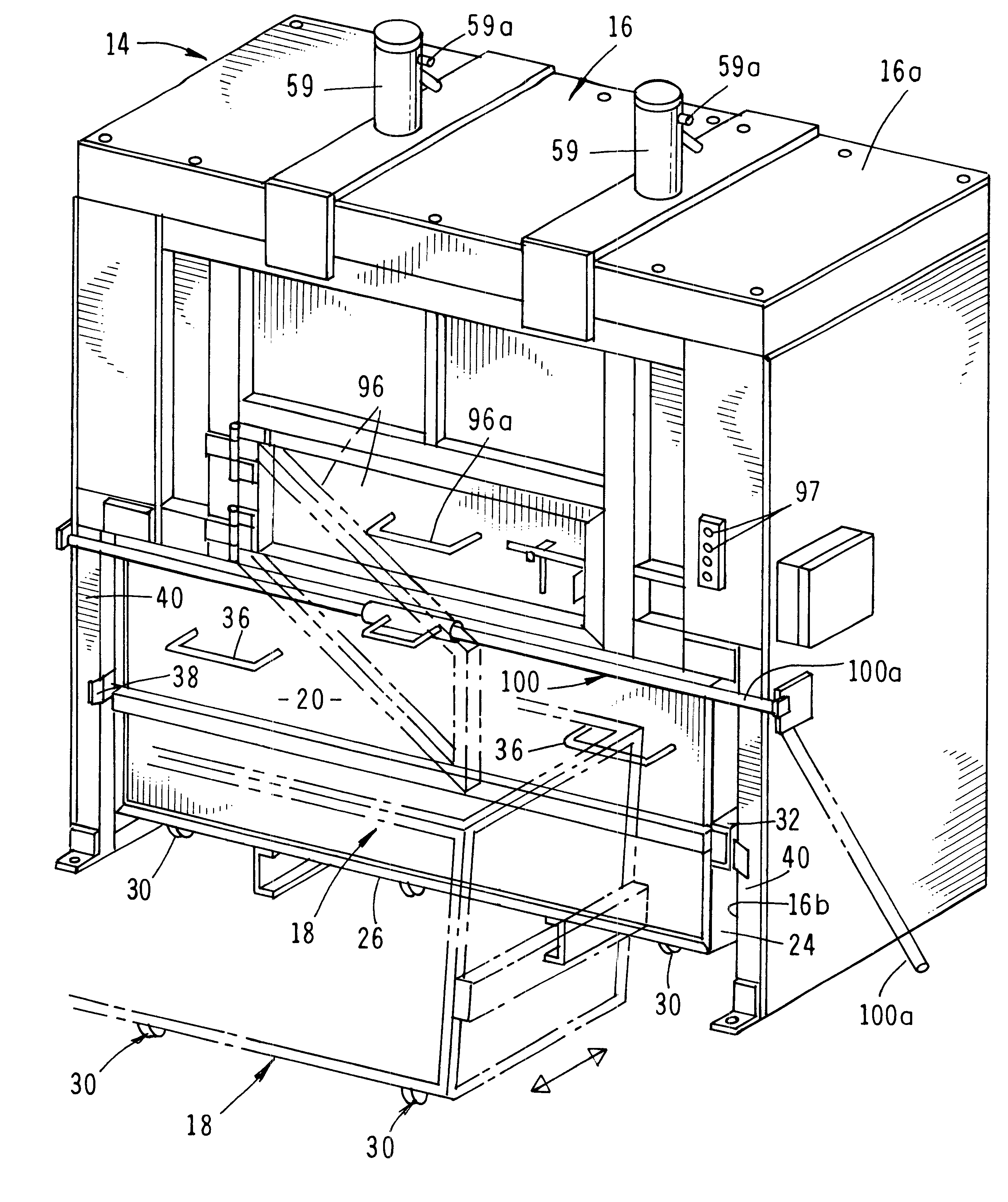
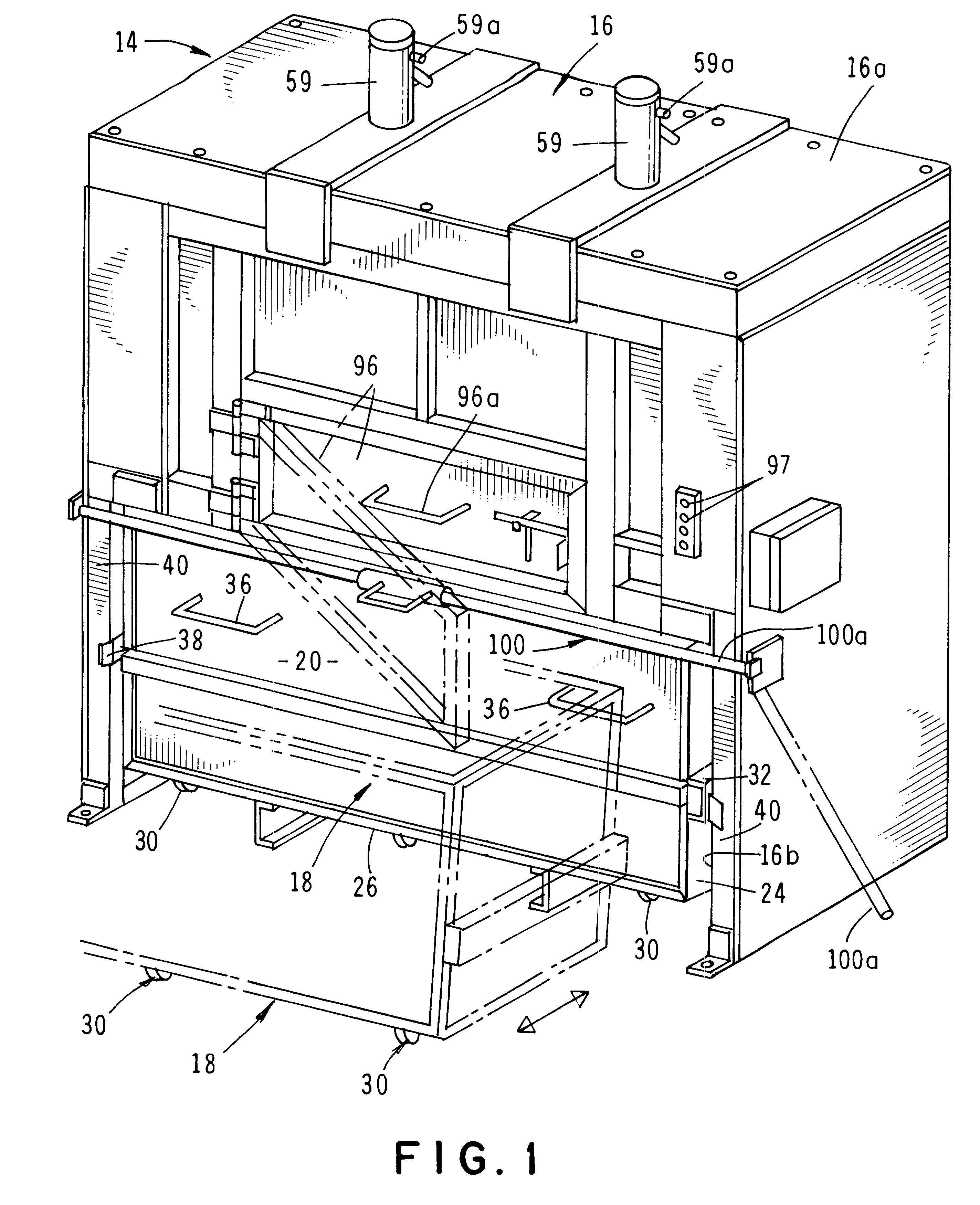
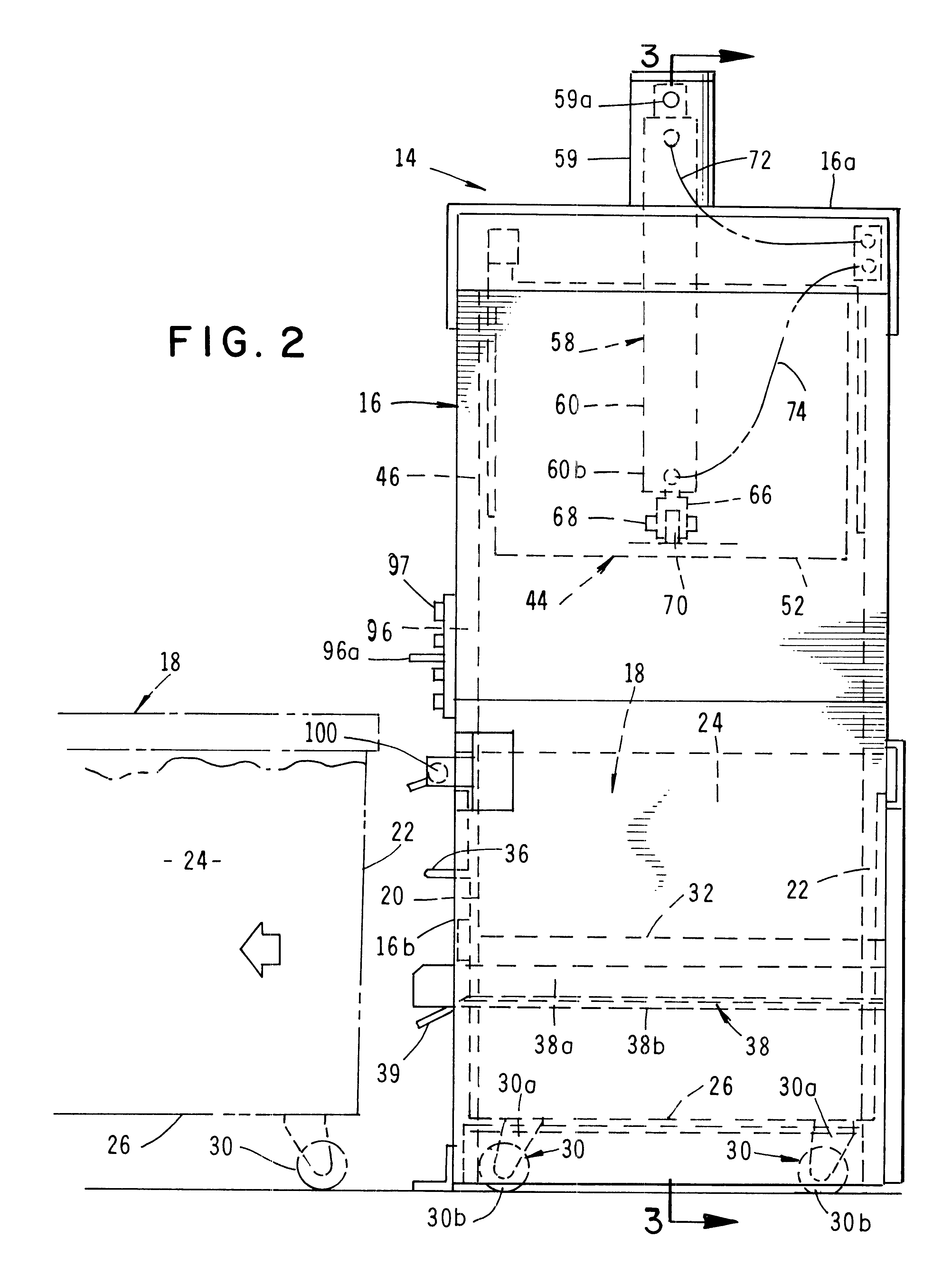
Referring to the drawings and particularly to FIGS. 1, 2, 3A and 3B, one form of the apparatus for compacting waste is there shown and generally designated by the numeral 14. As indicated in FIG. 1, the apparatus comprises a housing 16 having a closed upper portion 16a and a front open lower portion 16b. Receivable within front open lower portion 16b is a top open container 18 for receiving the waste to be compacted. Container 18 is movable from a first position shown by the solid lines in FIG. 1 wherein the container is disposed within housing 16 to a second position shown by the phantom lines in FIG. 1 wherein the container is in an outwardly position relative to of housing 16.

As indicated in FIGS. 2, 3A and 3B, container 18 comprises a bin-like structure having interconnected front, rear, side and bottom walls 20, 22, 24, and 26 respectively. Interconnected with bottom wall 26 are a plurality of spaced apart caster assemblies 30. Caster assemblies 30 are of conventional construct...


PUM


Abstract

A vertical waste compactor that includes a pair of side-by-side packing rams that provide increased compaction force on waste materials contained within an open-top trash receiving container that can be conveniently moved inwardly and outwardly of a supporting frame that supports the dual packing rams. The packing rams are driven by a pair of hydraulically actuated assemblies that are supported by the device housing and are pivotally connected to the compaction rams.

Description

1. Field of the InventionThe present invention relates generally to a compactor for waste material. More particularly, the invention concerns a dual-ram, high-density, industrial-type vertical waste compacting apparatus.2. Discussion of the Prior ArtWaste production in the United States has reached enormous proportions and continues to increase. To better dispose of this waste and to relieve overburdened land fills, a number of different types of home and industrial type trash compactors have been suggested.Home trash compactors are usually quite small and generally comprise a small, vertically operated ram which moves within a small trash compactor body to compact domestic type waste materials placed into the body. Industrial-type trash compactors, are generally much larger than home trash compactors, and typically comprise either pivotally mounted or vertically operated ram components that compact trash disposed within a container of several cubic foot capacity allowing the waste ...

Claims


Application Information

Patent Timeline
IPC IPC(8): B30B9/00B30B9/30
CPCB30B1/34B30B1/36B30B9/3057B30B9/3021B30B9/3042B30B9/3007
Inventor WALES, JR., HAL
Owner WALES JR HAL
Why Eureka
Try Eureka