Connecting terminal and method of mounting the same onto a circuit board

a technology of connecting terminals and circuit boards, applied in the direction of connection contact material, connection connection, non-printed electric components of printed circuits, etc., can solve the problems of difficult to maintain conduction, limited movable range, and inability to maintain elastic force as designed

Inactive Publication Date: 2003-04-22
JST MFG CO LTD
View PDF4 Cites 34 Cited by
  • Summary
  • Abstract
  • Description
  • Claims
  • Application Information

AI Technical Summary

Problems solved by technology

If the contact part 140 is repeatedly elastically deformed, the solder fixed part is peeled off and cracked, thereby making it difficult to maintain the conduction.
However, when the sealed panel and the like is pressed down or compressed oblique or in the lateral direction, which is caused by the deviation of the sealed panel, the spring contact 311 is crushed in the lateral direction and is irregularly deformed, so that there arises a possibility that an elastic force as designed cannot be maintained.
However, when the spring contact 311 having such a construction is excessively pressed down by a sealed panel and the like, the tip end of the contact comes into contact with the substrate part, and hence the movable range is limited, making it difficult to keep an optimum elastic force.

Method used


Image

  • Connecting terminal and method of mounting the same onto a circuit board
  • Connecting terminal and method of mounting the same onto a circuit board
  • Connecting terminal and method of mounting the same onto a circuit board

Examples


Embodiment Construction

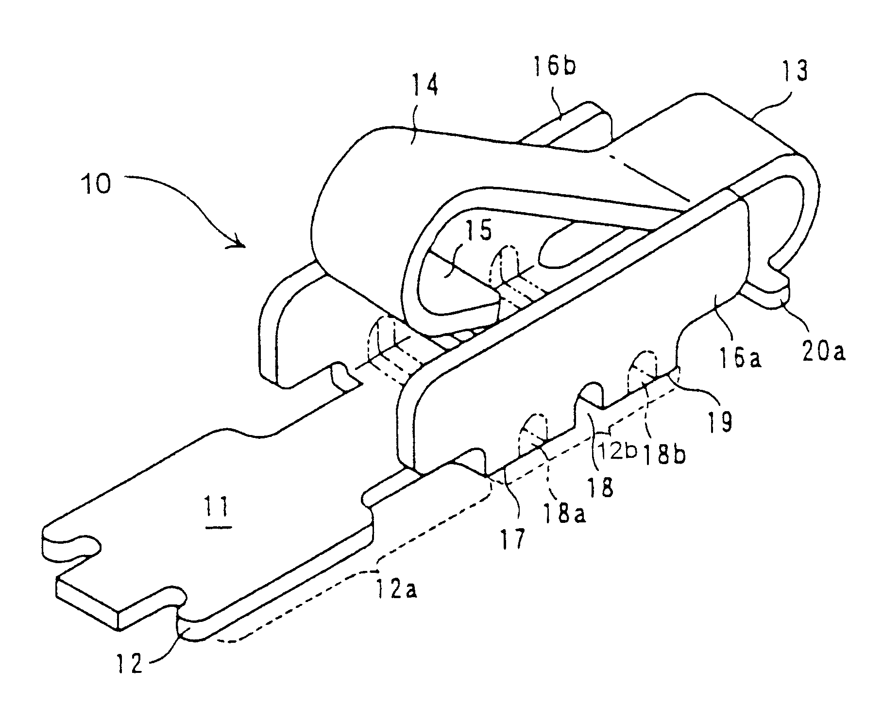
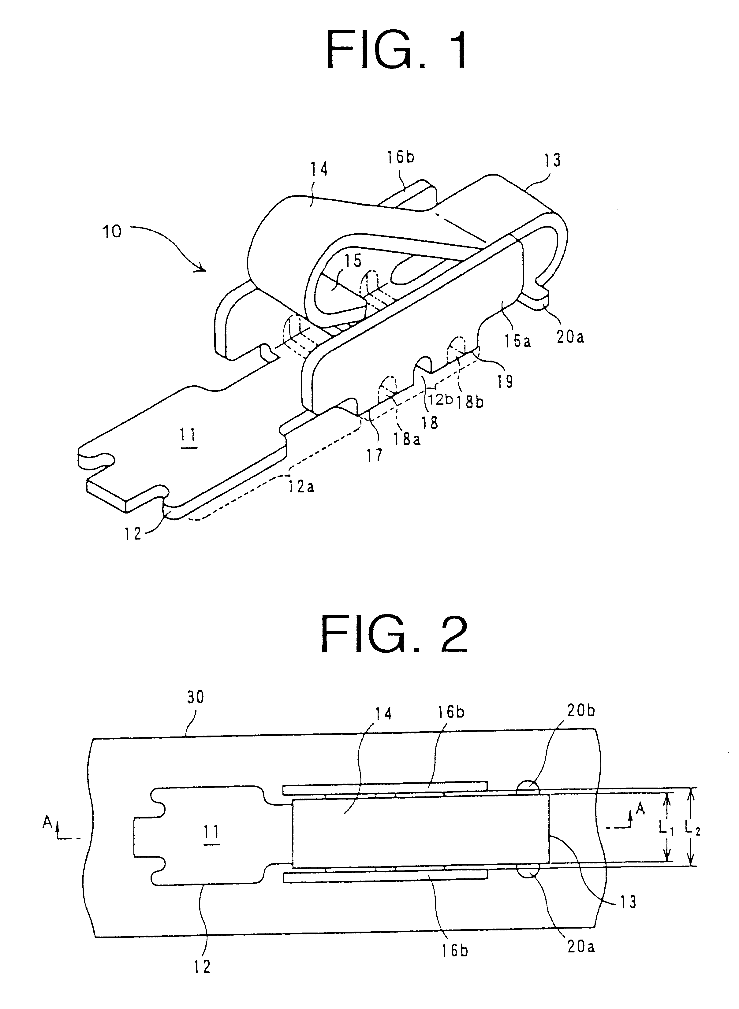
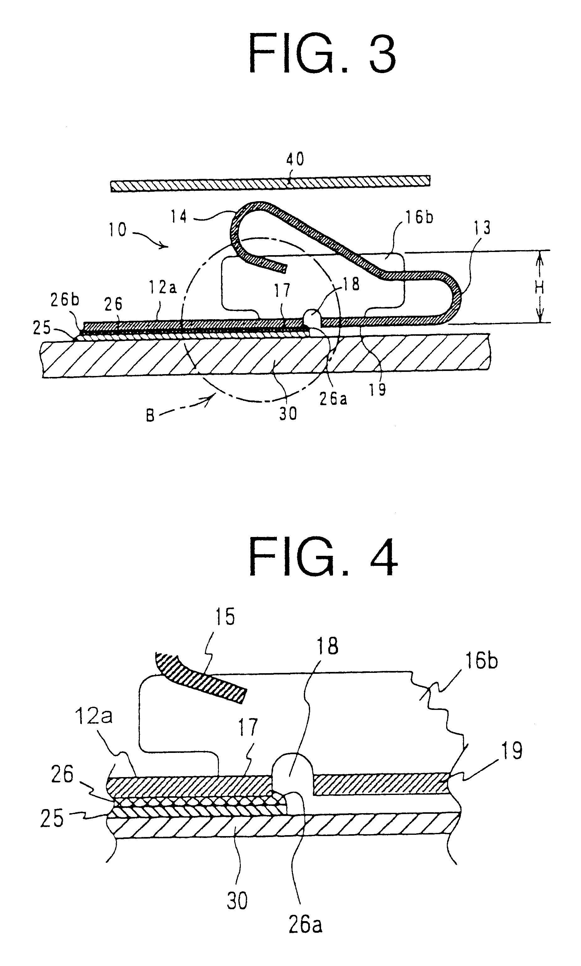
A preferred embodiment of a connecting terminal which embodies the invention is described with reference to the attached drawings. A connecting terminal according to the preferred embodiment and a state where the connecting terminal is mounted onto a circuit board are illustrated in FIGS. 1 to 3. FIG. 1 is a perspective view showing the entire connecting terminal according to the preferred embodiment of the invention, FIG. 2 is a plan view showing a state where the connecting terminal is mounted onto the circuit board according to the preferred embodiment of the invention, and FIG. 3 is a side sectional view taken along the line A--A in FIG. 2. The flat conductor 40 is omitted in FIG. 2.

As shown in FIG. 1, a connecting terminal 10 according to the preferred embodiment is made of a conductive plate 11 having substantially a strip shape prepared by punching a conductive metal plate. The connecting terminal 10 is made of a conductive plate 11 and comprises a fixed part 12 which is prov...


PUM


Abstract

A connecting terminal for allowing a circuit board to come into compression contact with a flat conductor with certainty, particularly to a connecting terminal having a contact part which is not irregularly deformed even if the contact part comes into compression contact with the flat conductor oblique or in the lateral direction and which maintains an optimum contact pressure. The connecting terminal is made of a substantially strip conductive plate and comprises a fixed part provided at one end of the conductive plate to be mounted onto a circuit board, and a contact part extended from the fixed part and formed by bending the conductive plate toward the fixed part to form a curved part, wherein the contact part is elastically deformed about the curved part to come into compression contact with the substantially flat conductor, and the connecting terminal further comprises a pair of side wall parts formed by bending the conductive plate 11 at the fixed part in a width direction thereof, wherein the side wall parts have a height to an extent to restrict excessive deformation of the contact part when the contact part comes into compression contact with the flat conductor. Further, an interval between the pair of side wall parts is made larger than a width of the contact part, and both end sides of the contact part contact or approach inner surfaces of the side wall parts.

Description

1. Field of the InventionThe invention relates a terminal to be connected onto a circuit board (hereinafter referred to as connecting terminal) and a method of mounting the same onto the circuit board, particularly to a connecting terminal which is effective in cases where the circuit board is grounded to another circuit board, sealing plate, a chassis, a case frame, and the like so as to prevent an electromagnetic field produced from a high frequency circuit used in a portable telephone and the like from influencing upon other devices, and a method of mounting the connecting terminal onto the circuit board.2. Description of the Related ArtA grounding terminal has been already known since it has been disclosed, e.g., in Japanese Patent No. 3,068,557 and Japanese Utility Model Registration No. 3,064,756, wherein a grounding terminal is mounted onto a circuit board, i.e., printed circuit board and it comes into compression contact with a grounding conductor, thereby grounding the prin...

Claims


Application Information

Patent Timeline
Patent Type & Authority Patents(United States)
IPC IPC(8): H01R13/24H01R13/22H01R4/64H01R4/02H05K1/18H05K3/34H05K7/14
CPCH01R13/2442
Inventor ORIHARA, MASAYUKI
Owner JST MFG CO LTD
Why Eureka
Try Eureka