Method and apparatus for manufacturing painted or varnished parts out of molded plastics material

a technology of molded plastics and manufacturing methods, applied in the direction of molds, moldings, domestic objects, etc., can solve the problems of fragile parts, relatively high implementation costs, and unsatisfactory aesthetics, and achieve the effect of reducing paint loss

Inactive Publication Date: 2003-05-06
LOREAL SA
View PDF9 Cites 44 Cited by
  • Summary
  • Abstract
  • Description
  • Claims
  • Application Information

AI Technical Summary

Benefits of technology

By means of the invention, it is possible to obtain a pearly or other surface appearance without any need to add a filler to the thermoplastic material, thereby solving the problems of traces left by the flow lines of the material.
The invention makes it possible to use a thermoplastic material that has no filler or coloring agent, that is entirely compatible with the composition that is to be contained inside the flask, while nevertheless obtaining the looked-for external appearance, since there is no risk of the pigments or coloring agents in the paint used coming into contact with the above-mentioned composition.

Problems solved by technology

Nevertheless, the flow lines of the material during molding usually remain visible on the part made in that way, which can be esthetically unpleasing.
Furthermore, the presence of the filler can give rise to problems with the part being fragile.
Also, to give a metallic appearance to parts made of molded plastics material, it is known to subject them to vacuum metallization or to immerse them in an electrolytic bath, but those techniques are relatively expensive to implement.
It is known that parts made of plastics material can be painted by spraying paint or varnish thereon, however that solution remains relatively expensive and can also give rise to environmental problems.
That method requires a mold that is relatively complicated since the displacement of the component parts of the mold must be controlled accurately prior to injecting paint.
That method is relatively difficult to implement since the capacity for compression of the plastics material depends on the thickness of the non-solidified layer in the core of the part.
The shape of the part must therefore be implemented accordingly, thereby complicating design.

Method used


Image

  • Method and apparatus for manufacturing painted or varnished parts out of molded plastics material
  • Method and apparatus for manufacturing painted or varnished parts out of molded plastics material
  • Method and apparatus for manufacturing painted or varnished parts out of molded plastics material

Examples


Embodiment Construction

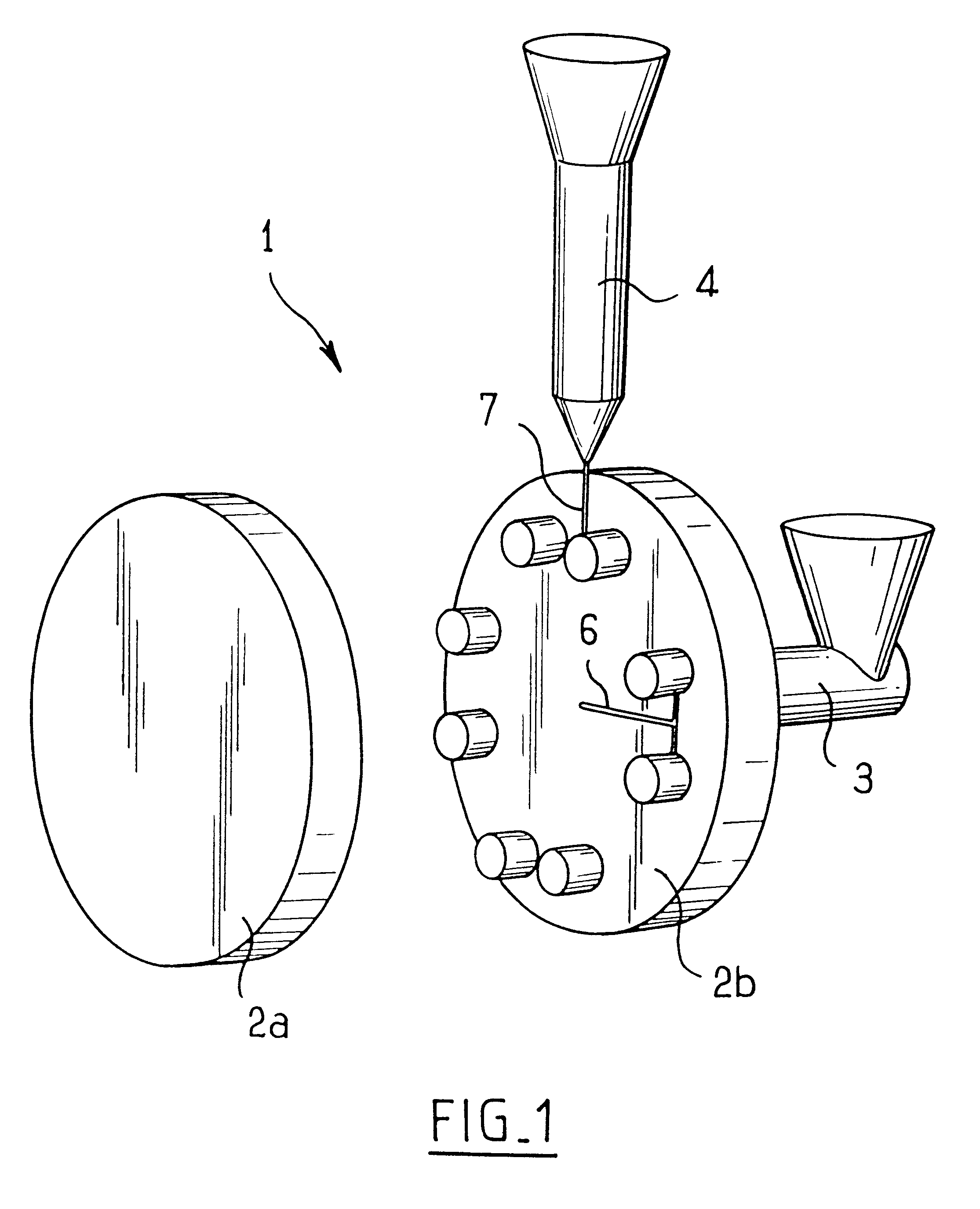
The apparatus 1 shown in FIG. 1 comprises a two-portion rotary mold 2a, 2b, a feed member 3 for feeding the thermoplastic material that is to be molded, and a feed member 4 for feeding the paint.

In the embodiment shown, the mold 2a, 2b is designed to manufacture caps for closing aerosol cans.

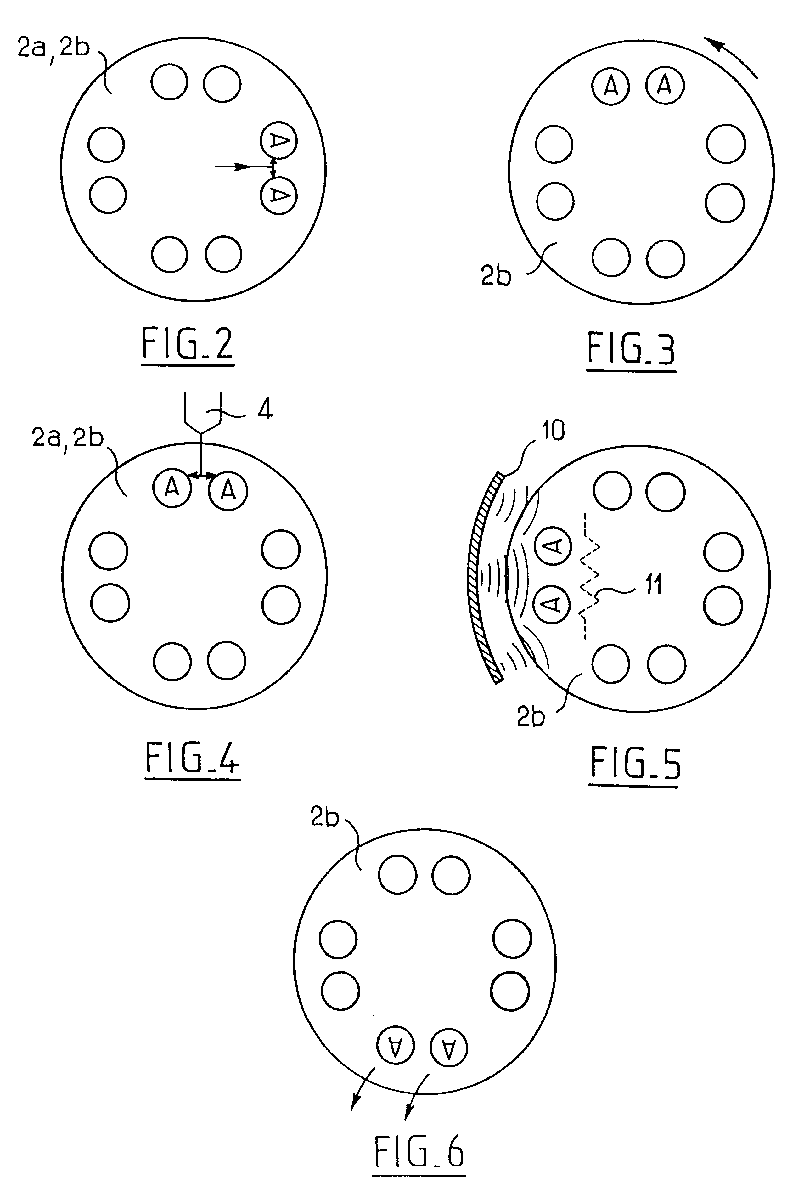
Channels 6 are made in the mold 2a, 2b so that when the mold is closed, they lead thermoplastic material in the molten state from the member 3 to the cavities 5 in the mold in which the parts are to be molded.

The cavities 4 are of identical dimensions and they are defined by shapes formed in or on the portions 2a and 2b.

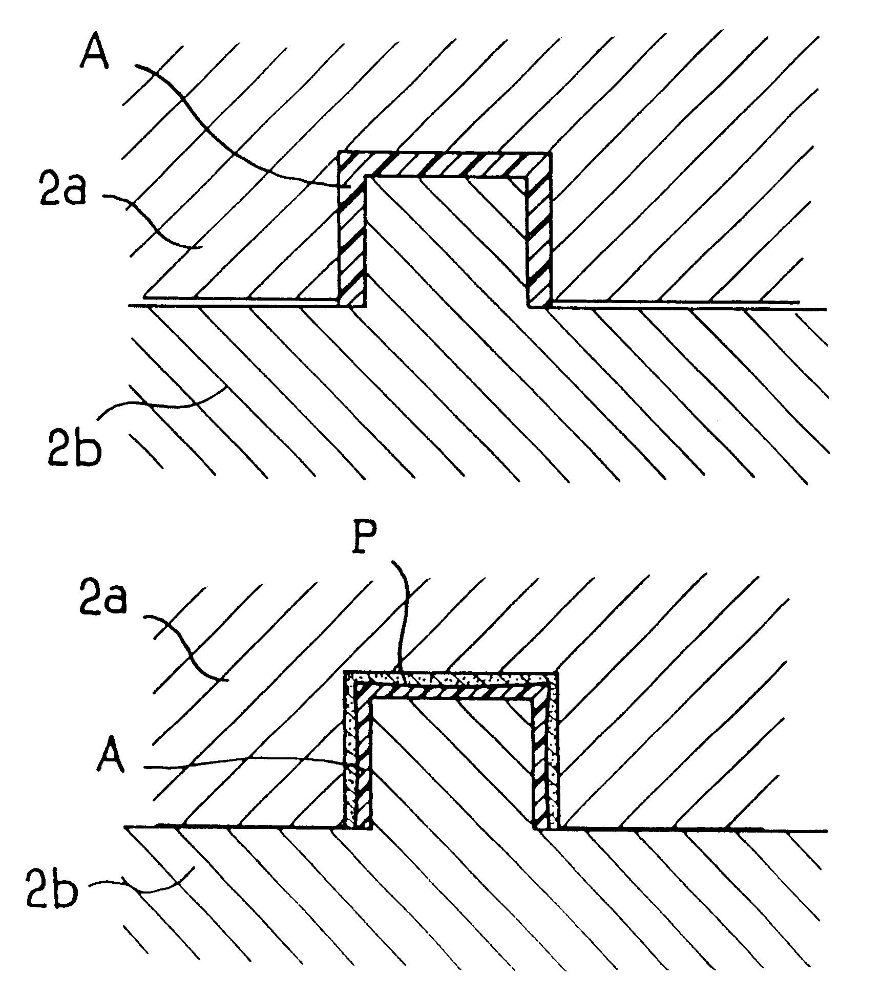
In the example shown, each cavity 5 is defined by the space that exists between a recess 8 in the portion 2a and a projection 9 on the portion 2b which is received inside the recess 8.

A cavity 5 is shown in isolation in FIG. 7.

Mold portion 2b also has channels 7 for use when the mold is closed to bring paint in the liquid state from the member 4 into each cavity 5 around a previo...


PUM

PropertyMeasurementUnit
temperatureaaaaaaaaaa
thicknessaaaaaaaaaa
thicknessaaaaaaaaaa

Abstract

A method of making a painted part out of molded thermoplastic material, the method including making the part to be painted by a method of molding thermoplastic material in the cavity of a mold; allowing the part made in this way to cool at least on the surface, cooling being accompanied by shrinkage, and being performed by opening the mold that was used to make the part that is to be painted; and injecting paint around the part in a cavity of a mold having the same shape as the mold cavity that was used for molding the thermoplastic material.

Description

The present invention relates to manufacturing parts by molding thermoplastic material, and more particularly but not exclusively, to manufacturing parts having a surface appearance that is pearly or metallic.To confer a pearly appearance to parts made of molded plastics material, it is known to incorporate an appropriate filler in the plastic.Nevertheless, the flow lines of the material during molding usually remain visible on the part made in that way, which can be esthetically unpleasing.Furthermore, the presence of the filler can give rise to problems with the part being fragile.Also, to give a metallic appearance to parts made of molded plastics material, it is known to subject them to vacuum metallization or to immerse them in an electrolytic bath, but those techniques are relatively expensive to implement.It is known that parts made of plastics material can be painted by spraying paint or varnish thereon, however that solution remains relatively expensive and can also give ri...

Claims


Application Information

Patent Timeline
Patent Type & Authority Patents(United States)
IPC IPC(8): B29C37/00B29C45/16B29C45/00
CPCB29C37/0028B29C45/1679B29C45/0013B29L2031/565B29C2045/1662B29K2101/12
Inventor BETHUNE, ALAIN
Owner LOREAL SA
Why Eureka
Try Eureka