Combination structure of electronic equipment

a technology of electronic equipment and combination structure, which is applied in the direction of electrical apparatus casings/cabinets/drawers, connection contact material, semiconductor/solid-state device details, etc., can solve the problems of complex construction, difficult assembly operation, and complicated construction of the connection-incorporating casing 2

Inactive Publication Date: 2003-05-06
FUJITSU GENERAL LTD
View PDF14 Cites 64 Cited by
  • Summary
  • Abstract
  • Description
  • Claims
  • Application Information

AI Technical Summary

Problems solved by technology

Therefore, the connector-incorporating casing 2 has a complicated construction, and can not be easily formed, and besides the assembling operation is difficult.
In the combination structure shown in FIG. 15, the power connectors 4 and 5 and the control connector 3 are formed integrally with the connector-incorporating resin casing 2, and therefore the connector-incorporating resin casing 2 has a complicated construction, and can not be easily formed, and besides the assembling operation is difficult.
Particularly when the connectors are increased in size and when the number of memories increases, it is difficult to provide the connectors on the same side surface of the connector-incorporating resin casing 2.
The electronic control unit 1 is electrically connected to the exterior via wire harnesses, and when all of the connectors are not provided on the same side surface, the wire harnesses can not be easily arranged and installed, so that an installation space is increased.
And besides, the packing 22 is used between the lid 20 and the casing 2, and also the packing 23 is used between the casing 2 and the heatsink 21, and this increases the production cost.
However, the increase of the heatsink 21 in size results in the increase of the total size of the electronic control unit 1, which makes the size reduction of the electronic control unit 1 difficult.
Moreover, use of the large heatsink increases the manufacturing cost of the electronic control unit 1, which is inconvenient for the maker.

Method used


Image

  • Combination structure of electronic equipment
  • Combination structure of electronic equipment
  • Combination structure of electronic equipment

Examples


Embodiment Construction

The present invention will be described in detail with reference to the accompanying drawings.

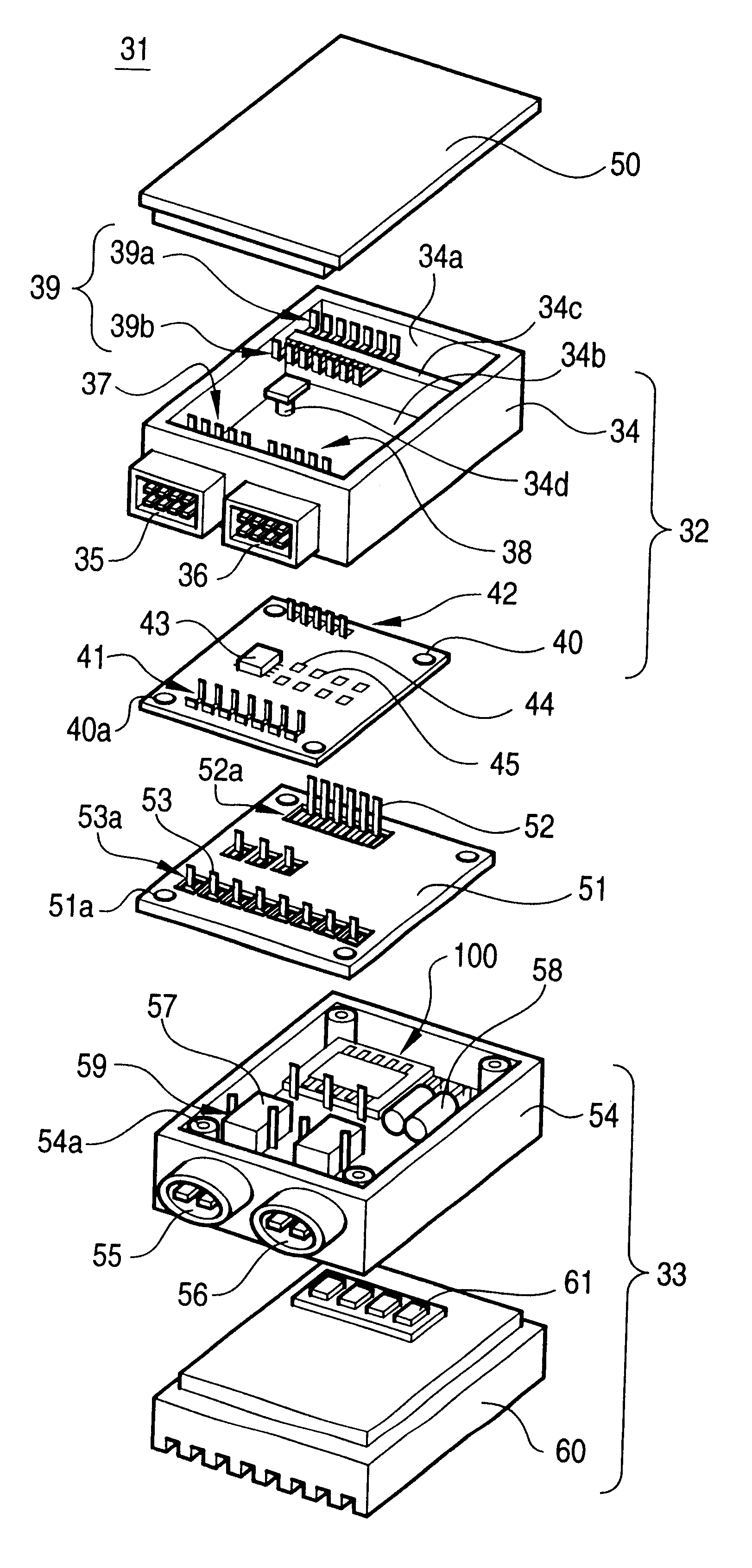
FIG. 1 roughly shows a combination structure of an electronic control unit 31 for mounting on a car, which is one preferred embodiment of an electronic equipment of the invention. The electronic control unit 31 is structurally divided into a control portion 32 and a power portion 33, and has such a structure that mounting of parts is easy, and that the two portions can be easily combined together. The control portion 32 comprises a control connector-incorporating casing (control casing) 34 which serves as a base portion for this control portion 32. The control connector-incorporating casing 34 is integrally molded of a synthetic resin, and has electrically-conductive metal portions partially embedded in a molded body thereof. An internal space of the control connector-incorporating casing 34 is divided into a first hollow portion 34a and a second hollow portion 34b by a wall 34c. The contro...


PUM


Abstract

An electronic control unit 31 for mounting on a vehicle include a control portion 32 and a power portion 33 which are separate from each other, and are combined together. A control board 40 is mounted on a control connector-incorporating casing 34, having control connectors 35 and 36 formed integrally thereon, thereby Forming the control portion 32. Connection terminals 41 on the control board 40 are soldered to connector connection terminals 37 and 38, embedded in the casing 34, and connection terminals 42 on the control board 40 are soldered to relay connection terminals 39 embedded in the casing 34. Power parts 57 and 58 are mounted on a power connector-incorporating casing 54, having power connectors 55 and 56 formed Integrally thereon, and further a heatsink is mounted on the casing 54, thereby forming the power portion 33. An intermediate layer 51 can be provided between the control portion 32 and the power portion 33. Parts can be mounted on the intermediate layer 51.

Description

1. Field of the inventionThis invention relates to a combination structure of an electronic equipment including an electrical control circuit portion and a power circuit portion for providing electric power.2. Description of the Related ArtElectronic control units (ECUs), each provided in a combined manner as a unit in accordance with the function of an object to be controlled, have heretofore been mounted on a vehicle. Each of the ECUs includes a control circuit portion (including a microcomputer or the like) for effecting a logical control operation, and a power circuit portion for controlling power to be fed to an exterior.FIG. 15 roughly shows a combination structure of a conventional electronic control unit 1. Main portions of the electronic control unit 1 are contained in a connector-incorporating resin casing 2. A control connector 3 and power connectors 4 and 5 are provided in a gathered manner on one side surface of the connector-incorporating resin casing 2. With this cons...

Claims


Application Information

Patent Timeline
Patent Type & Authority Patents(United States)
IPC IPC(8): H05K5/00H01R9/22H01R4/58
CPCH05K5/0065H01L2224/0603H01L2224/48091H01L2224/48227H01L2224/48465H01L2924/01079H01L2924/19041H01R9/226H01L2224/49112H01L2924/00014H01L2924/00
Inventor WAKABAYASHI, HIROYUKIOHTA, TAKASHI
Owner FUJITSU GENERAL LTD
Why Eureka
Try Eureka