Stored energy power system

Inactive Publication Date: 2003-05-06
VONBRETHORST WILLIAM F
View PDF10 Cites 161 Cited by
  • Summary
  • Abstract
  • Description
  • Claims
  • Application Information

AI Technical Summary

Benefits of technology

In order that the invention may be clearly understood and readily carried into effect, a preferred embodiment of

Problems solved by technology

This is expensive

Method used


Image

  • Stored energy power system
  • Stored energy power system
  • Stored energy power system

Examples


Embodiment Construction

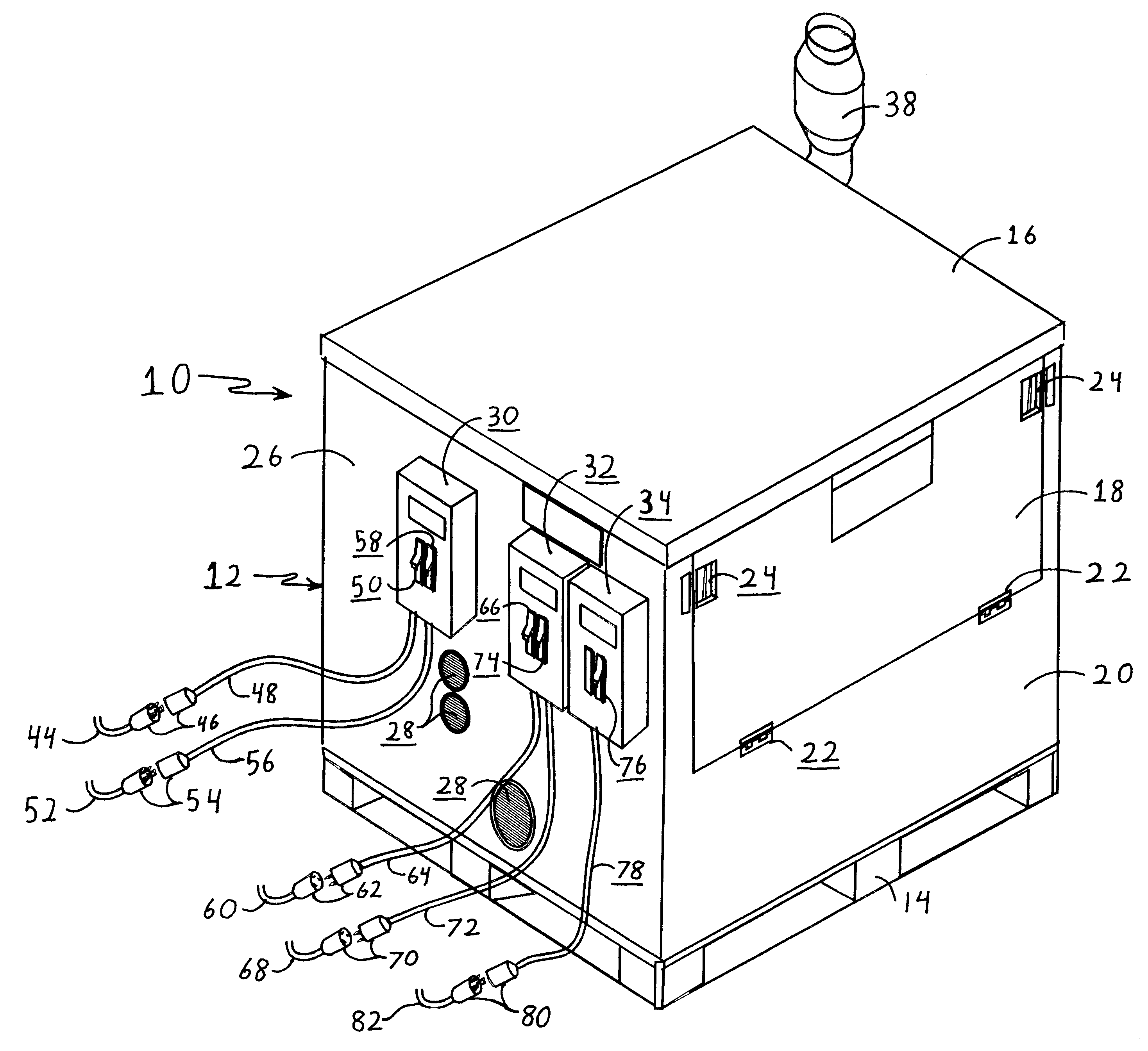
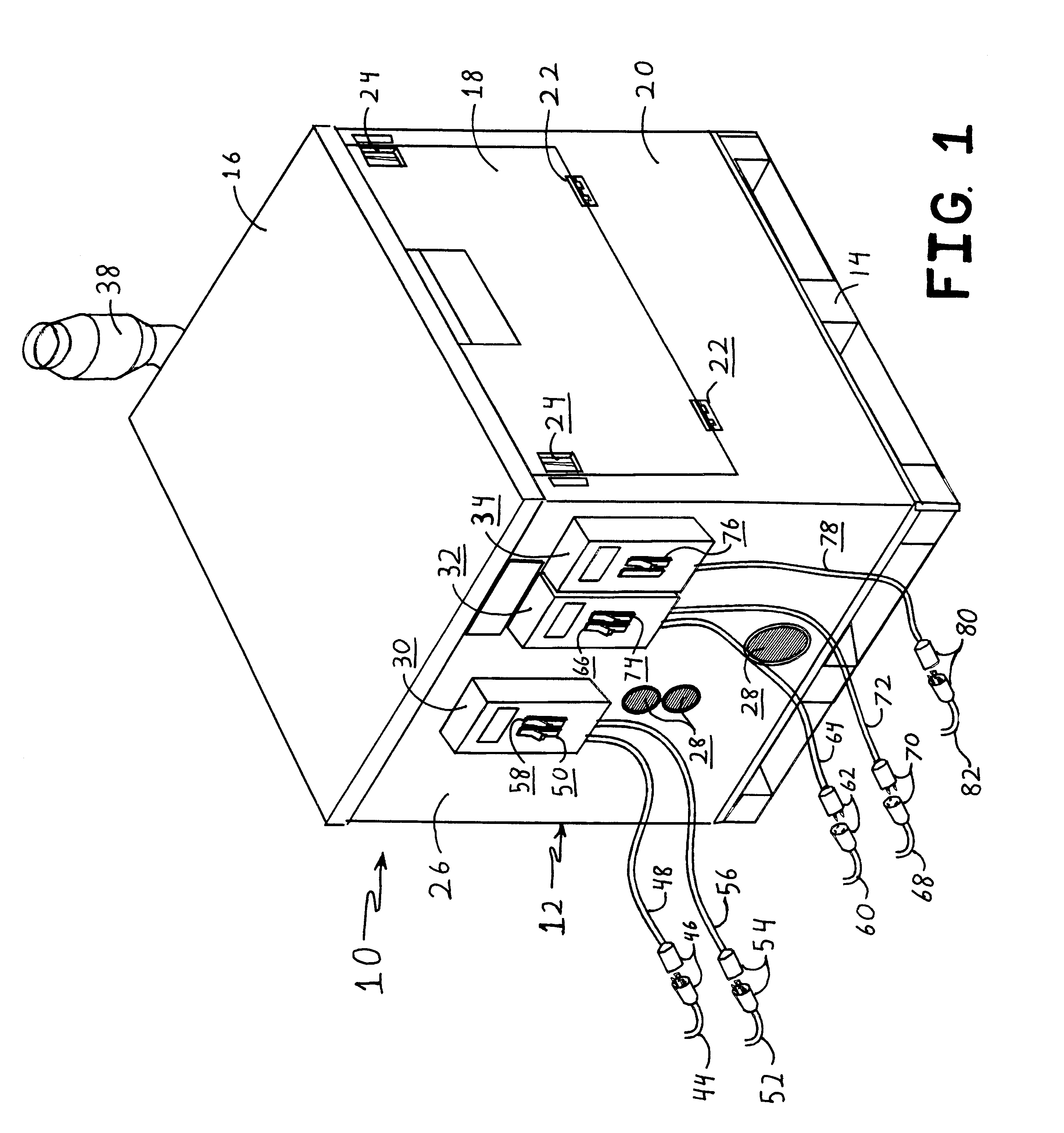
An electrical schematic of the stored energy power system 10 of the present invention is shown in FIG. 3. The stored energy power system 10 is housed in a housing 12, as shown in FIGS. 1 and 2. Components are mounted within the housing 12 in a conventional manner. The housing rests on a pallet stand 14 and has a removable top lid 16. The housing 12 is also provided with an inspection door 18 which is hingedly connected to a wall 20 of the housing 12 with hinges 22. A pair of latches 24 are used to secure the inspection door 18 in a closed position, as shown in FIG. 1. A wall 26 of housing 12 has three screen covered vent openings 28 as shown in FIG. 1. Further, three circuit breaker boxes 30, 32 and 34 are mounted to the outer face of wall 26, as shown in FIG. 1, in accordance with the National Electric Code.

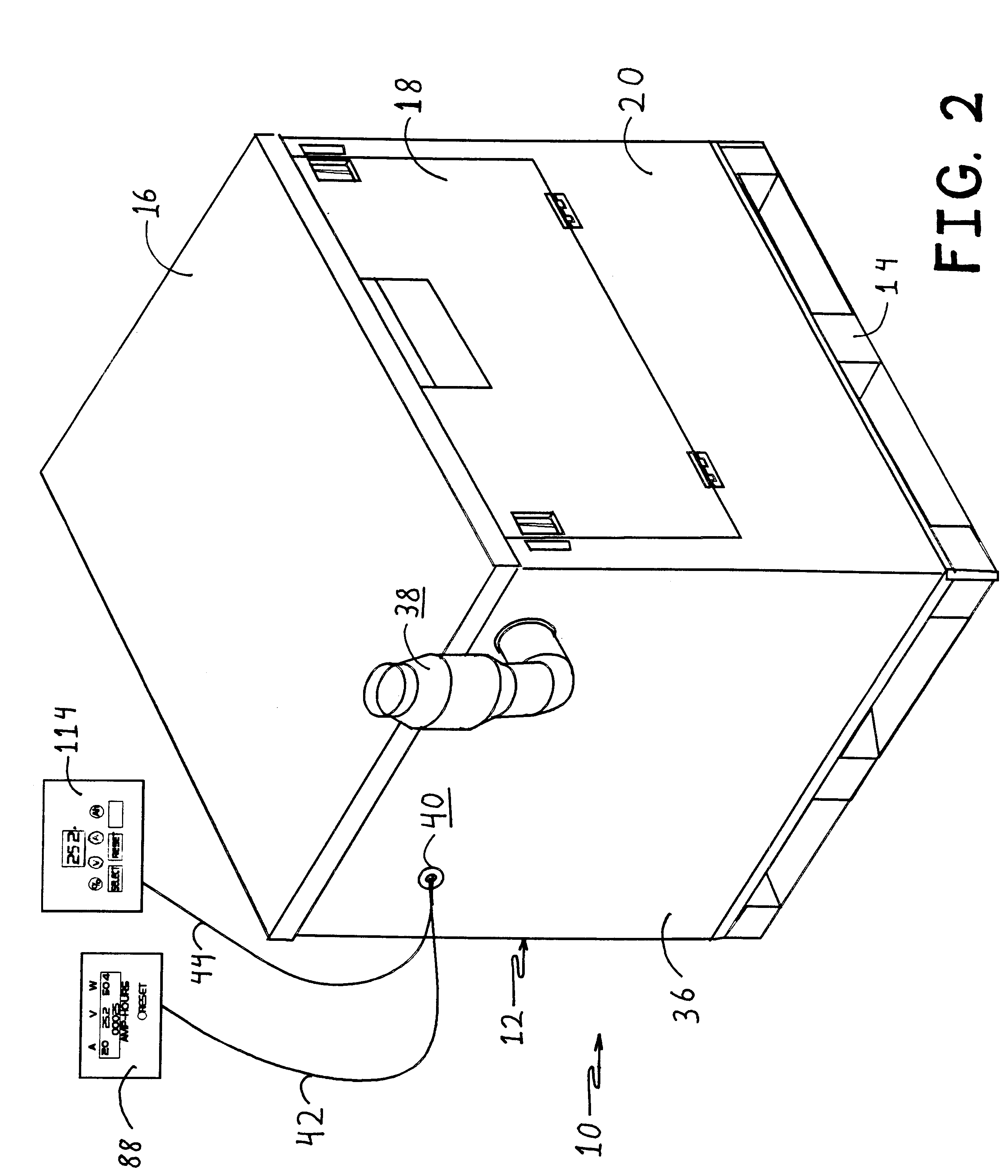
As shown in FIG. 2, a wall 36 of housing 12 has a fan exhaust pipe 38 mounted thereto. Further, a grommeted opening 40 is provided in wall 36 to allow cables 42 and 44 to exit f...


PUM


Abstract

A stored energy system is provided for delivering AC electrical power to a load. This system includes a single housing containing within a battery bank for storing DC power, and an inverter for receiving either DC power or AC power and converting DC power to AC power. The stored electrical system includes five circuit breakers mounted on the outside surface of the housing. Twist lock plugs are connected to each of the circuit breakers for removably connecting input power sources and output loads with the circuit breakers. A first circuit breaker is connected to a solar power source. A second circuit breaker is connected to a wind generator. A third circuit breaker is connected to a generator for generating AC power. A fourth circuit breaker is connected to a utility supplying AC power. A fifth circuit breaker is connected to the outside AC power load.

Description

The present invention relates to an electrical battery storage system enclosed in a single housing ready for connecting directly to solar and / or wind electrical power generation systems and further ready to be connected directly to a home electrical system, for example.A need exists for a single "plug-in" unit which can be used with persons using alternate sources of energy such as wind or solar power. A need exists for a unit which can be plugged into these solar and wind power generation systems and then convert the DC power obtained from these alternate sources to AC current which can then be used in a home, for example, to power lights and other electrical appliances. In the past, when solar or wind power has been used as an alternate source for home power, it has been necessary to hire an electrician to wire all the components together. This is expensive and time consuming. The present invention meets a need by providing a single unit which is a "plug-in" type unit fully compli...

Claims


Application Information

Patent Timeline
IPC IPC(8): H02J7/00
CPCH02J7/0055H02J7/0042H02J2207/40
Inventor VONBRETHORST, WILLIAM F.
Owner VONBRETHORST WILLIAM F
Why Eureka
Try Eureka