Disk drive error recovery and defect management method

a technology of disk drive and error recovery, applied in the direction of digital signal error detection/correction, instruments, recording signal processing, etc., can solve the problems of inability to read and write data sectors do not always fit evenly between servo position fields, and disk drive media often contain defective areas. , the reliability of reading and writing data to a defective area is at best unreliable and often impossibl

Inactive Publication Date: 2003-05-06
STMICROELECTRONICS INC A DELAWARE
View PDF8 Cites 10 Cited by
  • Summary
  • Abstract
  • Description
  • Claims
  • Application Information

AI Technical Summary

Problems solved by technology

The relationship between the optimum linear bit density and optimum position feedback interval, however, is such that data sectors do not always fit evenly between servo position fields.
Disk drive media often contain defective areas.
Reading and writing data to a defective area is at best unreliable and often impossible.
A given size media defect becomes more apparent and affects more data as data is recorded more densely.
However, many times new defects, often called "latent defects", become apparent after the disk drive is put to use.
Some of the factors that may contribute to latent defects include undesirable head / media contact, an incomplete defect scan during the factory test process, and contamination, the latter being of particular concern on removable media type products such as the floppy disk.
When a new defect is discovered on a read operation it is often impossible in current systems to recover the data stored at the defective location.
When the data is unrecoverable, disk drive vendors typically choose to not perform the reallocation.
Rather, the data transfer is halted and an error is reported to the host computer.
Such errors result in catastrophic data loss.
If reallocation were to be attempted without recovering the correct data, the reallocated sector does not contain accurate data.
Hence, any future read accesses to the defective sector must be flagged so that a data error is reported to the host computer.
Anytime data may be incorrect the disk drive must be able to notify the host computer or the bad data will be transferred.
This complicates the disk firmware without recovering the data.
In addition, future read accesses must not perform subsequent reallocations (until correct data is written) else the spare pool of data sectors may be consumed during repeated attempts by the host computer to read the data.

Method used


Image

  • Disk drive error recovery and defect management method
  • Disk drive error recovery and defect management method
  • Disk drive error recovery and defect management method

Examples


Embodiment Construction

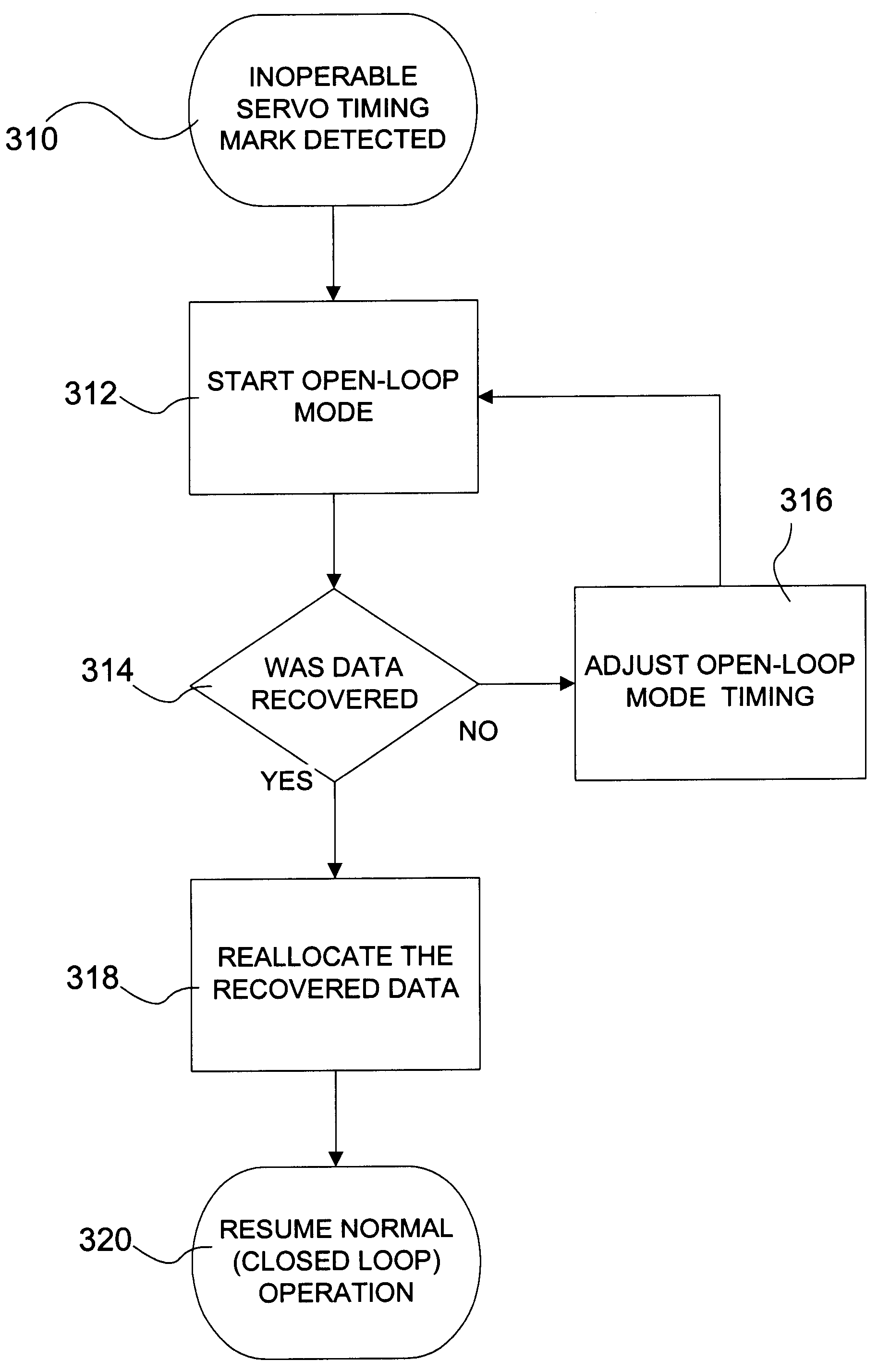
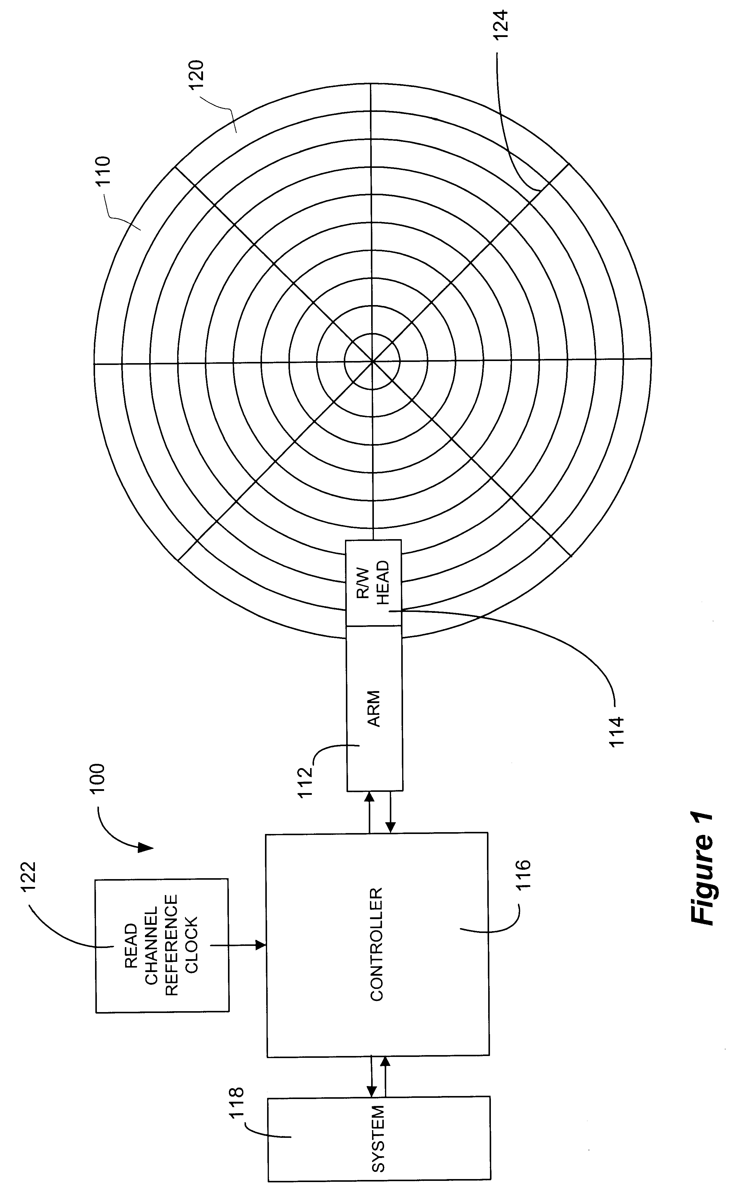
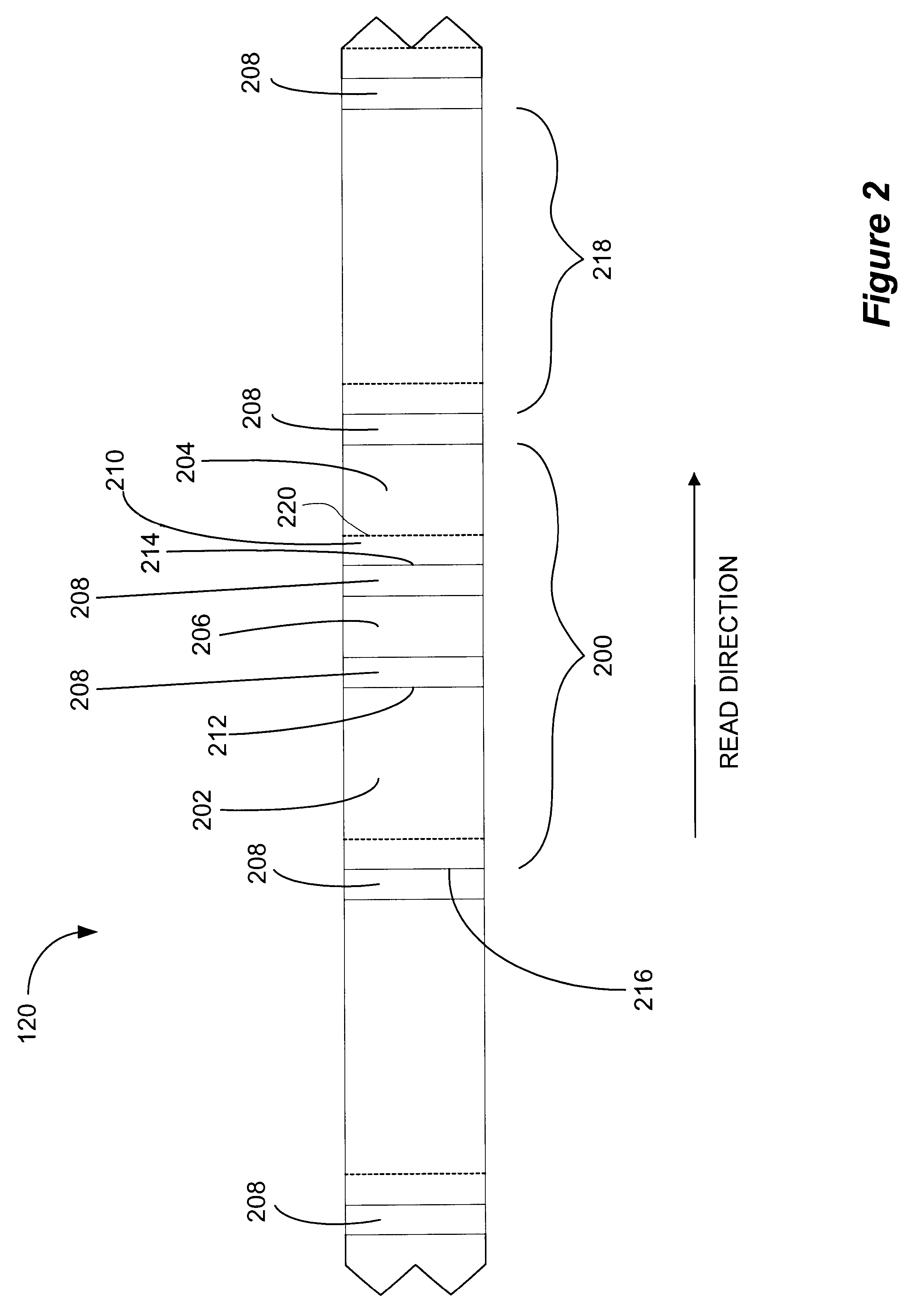
The present invention involves a method, computer implemented method, apparatus and computer program product that recovers data from a defective sector(s) of a storage media associated with an inoperable servo timing mark. As previously discussed, it is advantageous to use a servo position field's detected location as a timing reference to synchronize reading and writing data to the rotational position of the disk. However, a media defect may render a given servo position field unreadable thereby losing the timing reference. Before the present invention, once the timing reference is lost, the sector or sectors that rely on the servo position field as a timing reference are not usable and must be considered defective as well.

When an inoperable servo timing mark is discovered during a write operation, the system is able to use automatic reallocation because the data is readily available. However, when an inoperable servo timing mark is detected on a read operation, current systems are...


PUM

PropertyMeasurementUnit
delay timeaaaaaaaaaa
timeaaaaaaaaaa
spin speedaaaaaaaaaa

Abstract

A method, apparatus, computer implemented method and computer programmed product for recovering data from a split sector associated with an inoperable servo timing mark. Instead of using a servo timing mark to synchronize the read / write head to the spin speed variation of a storage media, the trailing end of the data fragment preceding the inoperable servo timing mark is used as a reference point. After detecting the reference point, the read operation is halted a predetermined delay time after which the read operation is resumed recovering the data from the sector relying on the inoperable servo timing mark.

Description

A. Field of the InventionThe present invention relates in general to data storage devices and, more particularly, to an apparatus, method, computer implemented method and computer programmed product for recovering data from a storage media.B. Background of the InventionComputers store data in various storage media often referred to as "memory." Memory may be implemented in, for example, hard disk, floppy disk, compact disk read only memory (CD-ROM), random access memory (RAM), one or more levels of cache devices and other available data storage media. Some storage media is circular or disk shaped. One example of a disk shaped storage media is the floppy disk. Data on a floppy disk is typically stored in circular tracks on the disk surface. Within a track, data is stored in "sectors." A sector represents the smallest addressable block of data. The amount of data recorded on a track is typically chosen based on the maximum linear bit density that can be supported by the head and media...

Claims


Application Information

Patent Timeline
Patent Type & Authority Patents(United States)
IPC IPC(8): G11B20/18G11B27/36G11B19/04
CPCG11B19/04G11B20/1883G11B27/36G11B2220/20G11B2020/183
Inventor WILSON, AARON WADE
Owner STMICROELECTRONICS INC A DELAWARE
Why Eureka
Try Eureka