Device for uniform shingle attachment to roof hip, ridge and barge rafter

Inactive Publication Date: 2003-05-13
CARPENTER RONALD
View PDF14 Cites 21 Cited by
  • Summary
  • Abstract
  • Description
  • Claims
  • Application Information

AI Technical Summary

Benefits of technology

FIG. 7 is a side cut away view of the device in FIG. 6 show

Problems solved by technology

Aesthetic concerns of modern roofing materials have presented an additional problem in mounting the shingles of hip, ridge and barge rafter intersections with the flat plane of the remainder of the roof.
Such materials, while offering longevity to the roof surface, generally lack sufficient thickness to provide a visual quality of a rise above the adjacent shingle to give the desired visual depth aesthetic quality.
Stated differently, the materials of asphalt fiberglass construction, are of such a thin and flat construction, they do not provide the aesthetic quality desired of many homeowners, who in the past have used wood shake or wood shingles which exhibit a stacking that appears thick from the shadows and actual thickness of such wood products.
This differing mounting technique is much harder to master and requires a roofing worker of a higher skill level than a worker installing normal plane mounted shingles.
Thus, costs are increased to the roofing contractor due to the level of skill required on hip and ridge intersections, an jobs can become delayed due to lack of skilled help.
Using different dye lots on colored roof is a ticket to aestheti

Method used


Image

  • Device for uniform shingle attachment to roof hip, ridge and barge rafter
  • Device for uniform shingle attachment to roof hip, ridge and barge rafter
  • Device for uniform shingle attachment to roof hip, ridge and barge rafter

Examples


Embodiment Construction

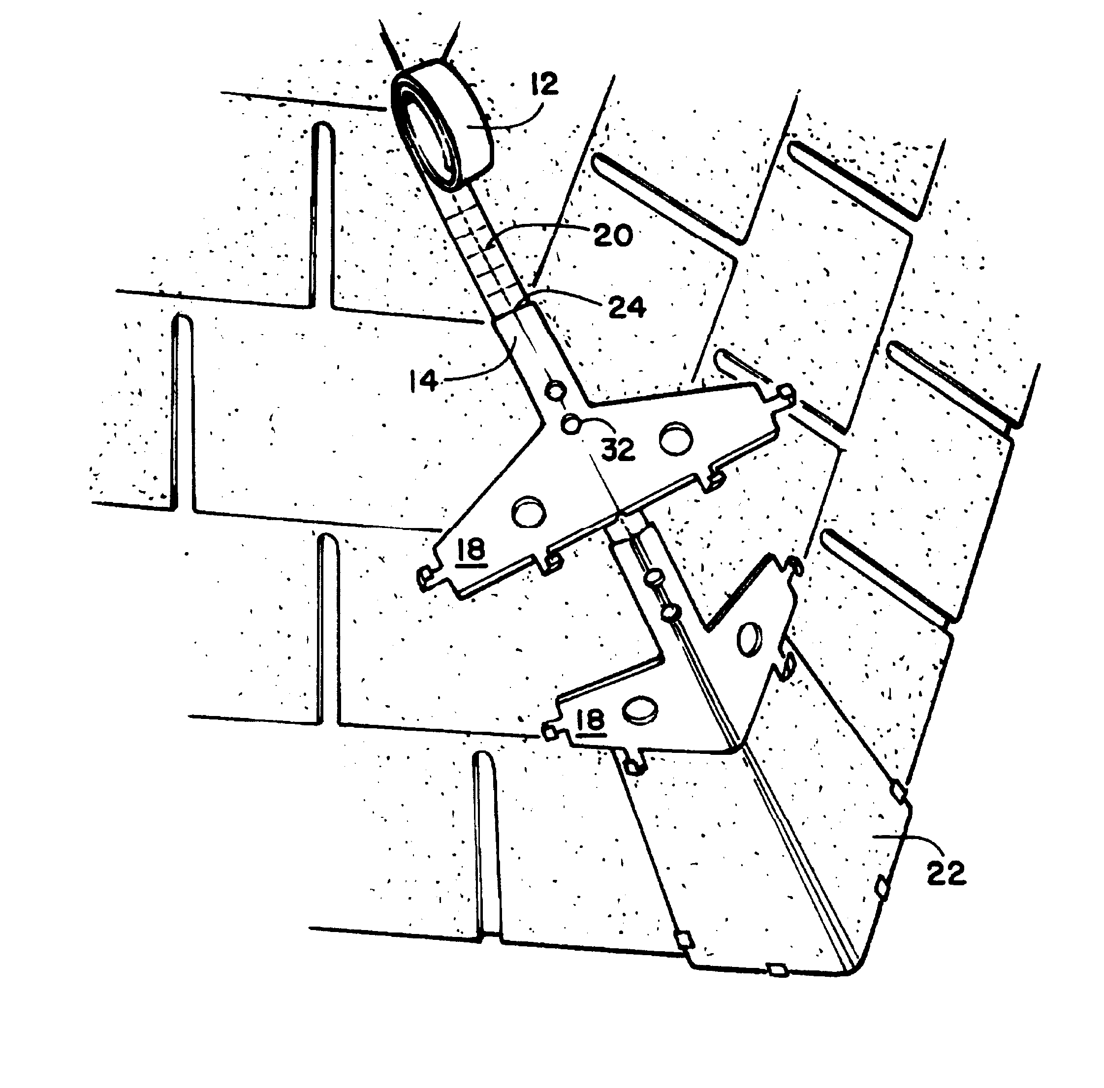
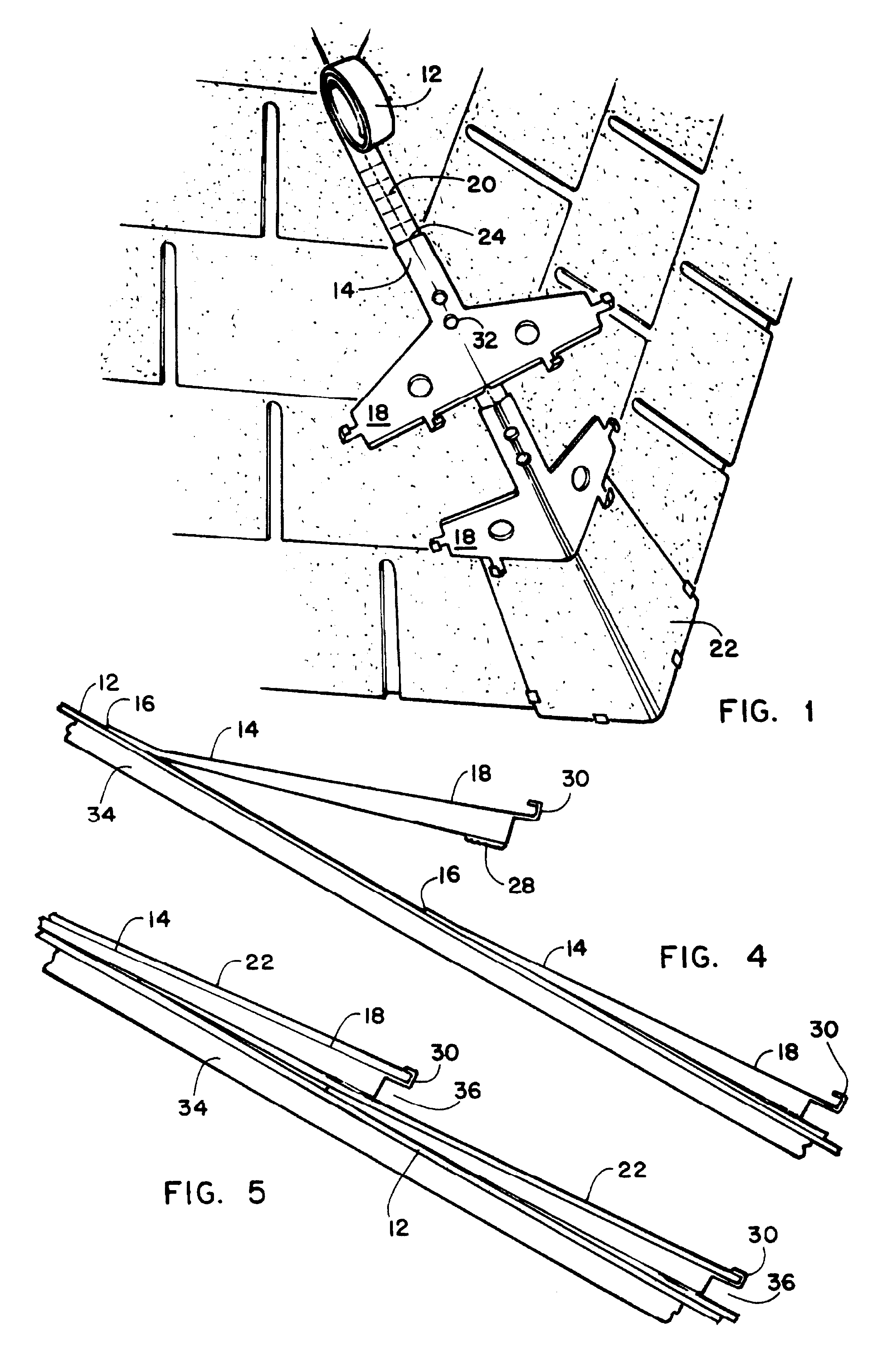
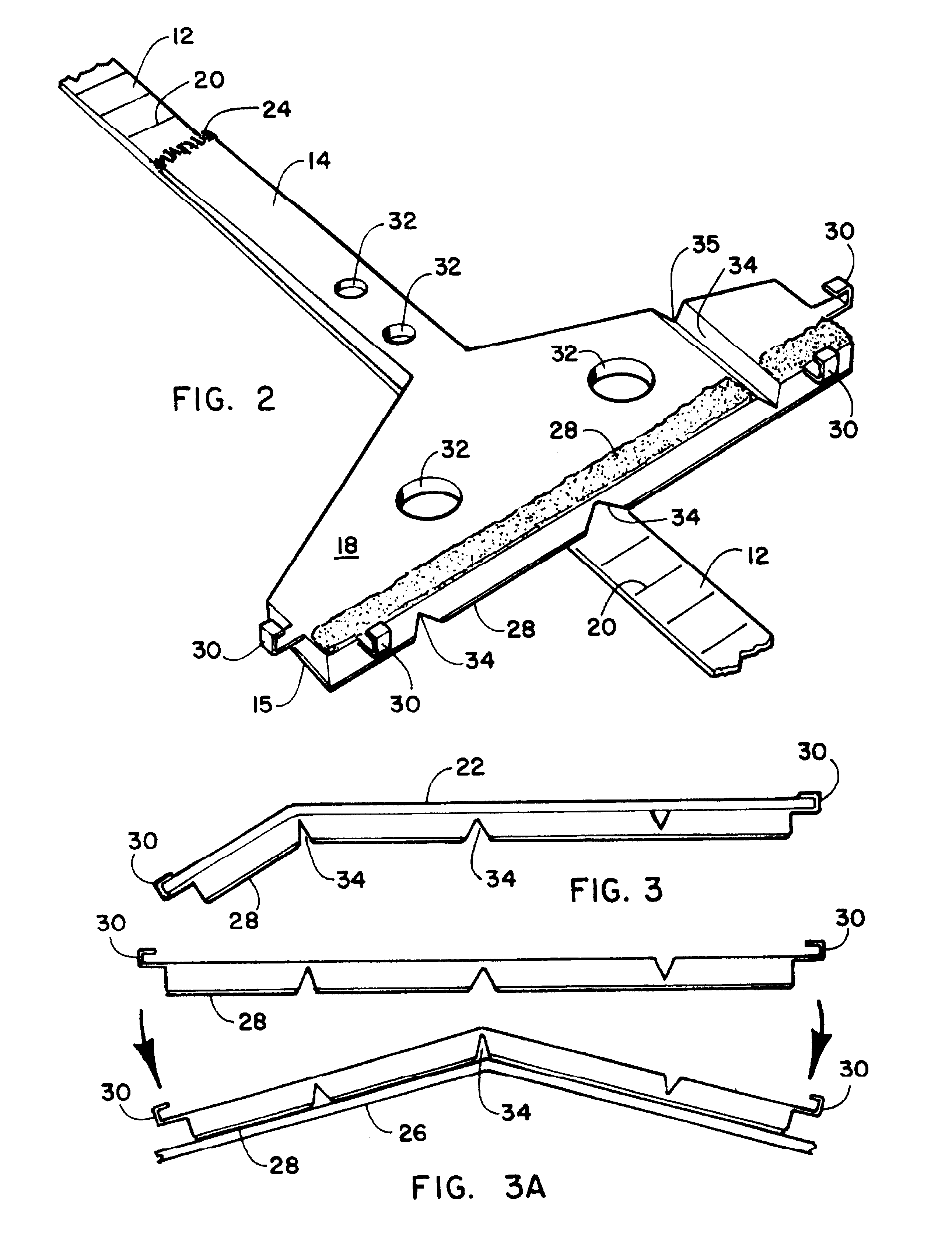
Referring now to the drawing Figures, specifically FIGS. 1 through 9 depict the preferred embodiments of the invention. FIG. 1 shows applicant's hip and ridge single mounting device 10 featuring the elongated runner or strap portion 12 which serves as the mount for the shingle fasteners 14. The elongated strap 12 is best constructed from a flexible material such as plastic, webbing, or wire mesh, or treated paper, or combinations thereof, such that when the individual shingle fasteners 14 are attached thereto, separation distance of the shingle fasteners 14 from each is maintained, while the strap is still flexible enough to allow for easy packaging, mounting and storage. Optionally, the elongated strap 12 cold be of a material that is slightly elastic in nature such as a rubber or other plastic or by including such materials as part of the aforementioned materials for construction of the strap 12. This would allow the elongated strap 12 to be stretched to adjust spacing of the shin...


PUM


Abstract

An apparatus for the attaching of shingles to a roof and especially to the hip, ridge, and barge rafter edge portions of a shingled roof. The device can provide both a mounting guide to aid the user to achieve an in-line installation of conventional roofing shingles as well as a user determined uniform rise of the shingles so mounted to achieve a desired visual depth or thickness to the roof. The device features an elongated base strap for mounting to the roof line and a plurality of shingle fasteners mounted to the base strap at distances optimal for the shingles being used. Use of adhesives and mechanical mounts for the attached shingle further aids in maintaining a secure mount of the attached shingles in high winds and inclement weather. Optionally, the device can function as an attic vent through venting of attic gasses to the atmosphere through a porus material in the gap between adjoining shingles or exhaust apertures communicating with attic venting apertures through an inner cavity of thee shingle fastener to cool the attic by convection.

Description

1. Field of the InventionThe present invention relates to an roofing and the shingle attachment thereto. More particularly it relates to an device providing an uniform and more secure attachment of shingles to the hip, ridge, and barge rafter portions of shingle roofing which allows for easy in-line installation of such shingles with a user defined spacing and rise.2. Prior ArtModern roofing uses a layering system wherein a base of roofing felt is mounted upon a wood roof and then covered by layers of shingles. Shingles mounted in such a manner generally overlap each other with the bottom portion of each shingle mounted to cover the top portion of the next shingle below. This provides a system whereby water running down a roof continuously falls to the upper surface of the next shingle down below its attachment point of that shingle to the roofing felt and underlying roof structure. Since water continuously seeks its own level due to gravity, the water running down a roof never enco...

Claims


Application Information

Patent Timeline
IPC IPC(8): E04D1/34E04D1/00E04D15/02E04D15/00E04D1/26E04D1/30
CPCE04D1/265E04D1/30E04D15/02E04D1/3402E04D2001/305E04D1/34
Inventor CARPENTER, RONALD
Owner CARPENTER RONALD
Why Eureka
Try Eureka