Connector assembly having a latching mechanism

a latching mechanism and connector technology, applied in the direction of incorrect coupling prevention, coupling device connection, electrical apparatus, etc., can solve the problems of insufficient mechanical strength of the hinge-shaped feet securing the lock arm to the second housing, the prior art structure can hardly ensure the one-to-one connection of the housings durable and strong, and the inability of the first housing to ensure the one-to-the-other durable and strong connection

Inactive Publication Date: 2003-05-13
JST MFG CO LTD
View PDF6 Cites 36 Cited by
  • Summary
  • Abstract
  • Description
  • Claims
  • Application Information

AI Technical Summary

Benefits of technology

In operation of coupling the male and female connectors, a considerably strong stress will be imparted to and accumulated in the supplementary resilient arm continuing from the lock arm's rear end, due to an elastic temporary deformation of this resilient arm. Elastic recovery will consequently be facilitated for the lock arm, thereby amplifying the feeling of snap-fit. Width and thickness of the supplementary resilient arm may be adjusted to give an optimal bending strength (elasticity) such that the lock arm has an increased rigidity enhancing relative interlock of the male and female housings, without making the connectors difficult to engage with and disengage from each other. Further, the guard for the lock arm will prevent wire ends of any foreign harness from catching the push lever or from unintentionally moving same to release the lock arm from the lockable lug.

Problems solved by technology

The prior art latching or interlocking mechanism formed in the connector assembly of this type is however disadvantageous in that the hinge-shaped feet securing the lock arm to the second housing are not of a sufficient mechanical strength.
Engagement of such a lock arm with such a lockable lug on the first housing can hardly ensure durable and strong connection of the housings one with another.
The prior art structure has thus often failed to ensure reliable electrical connections, when used in certain vibrating machines such as automobiles.
It is a further problem relevant to this drawback that `snap-fit` feeling has scarcely been produced when engaging the lockable lug with the lock arm, unfortunately making it difficult to confirm their mutual connection from outside.
If however mutual retention and mechanical strength of those lug and arm in the connectors would be designed excessively high, then they could not easily engage with or disengage from each other.
Due to such a gap, electric wire ends involved in adjacent harnesses have often pressed undesirably the push lever to unlock the lockable lug out of the lock arm.
This drawback has been most prominent in case of arranging a number of electric wire ends within such a narrow space as those in automobiles.
In addition, electric wire ends of the neighboring harnesses have sometimes got in the gap to be jammed therein, accidentally catching the push lever and hindering the wiring operations.

Method used


Image

  • Connector assembly having a latching mechanism
  • Connector assembly having a latching mechanism
  • Connector assembly having a latching mechanism

Examples


Embodiment Construction

Now some embodiments of the present invention will be described referring to the drawings.

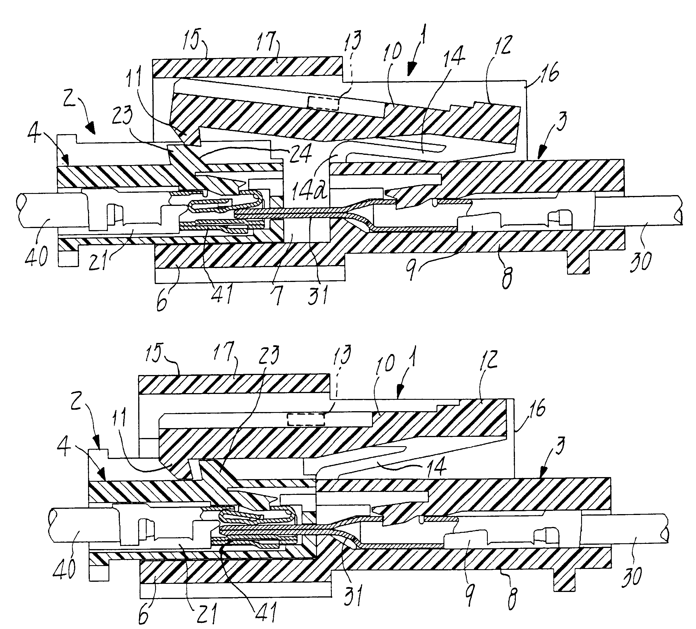
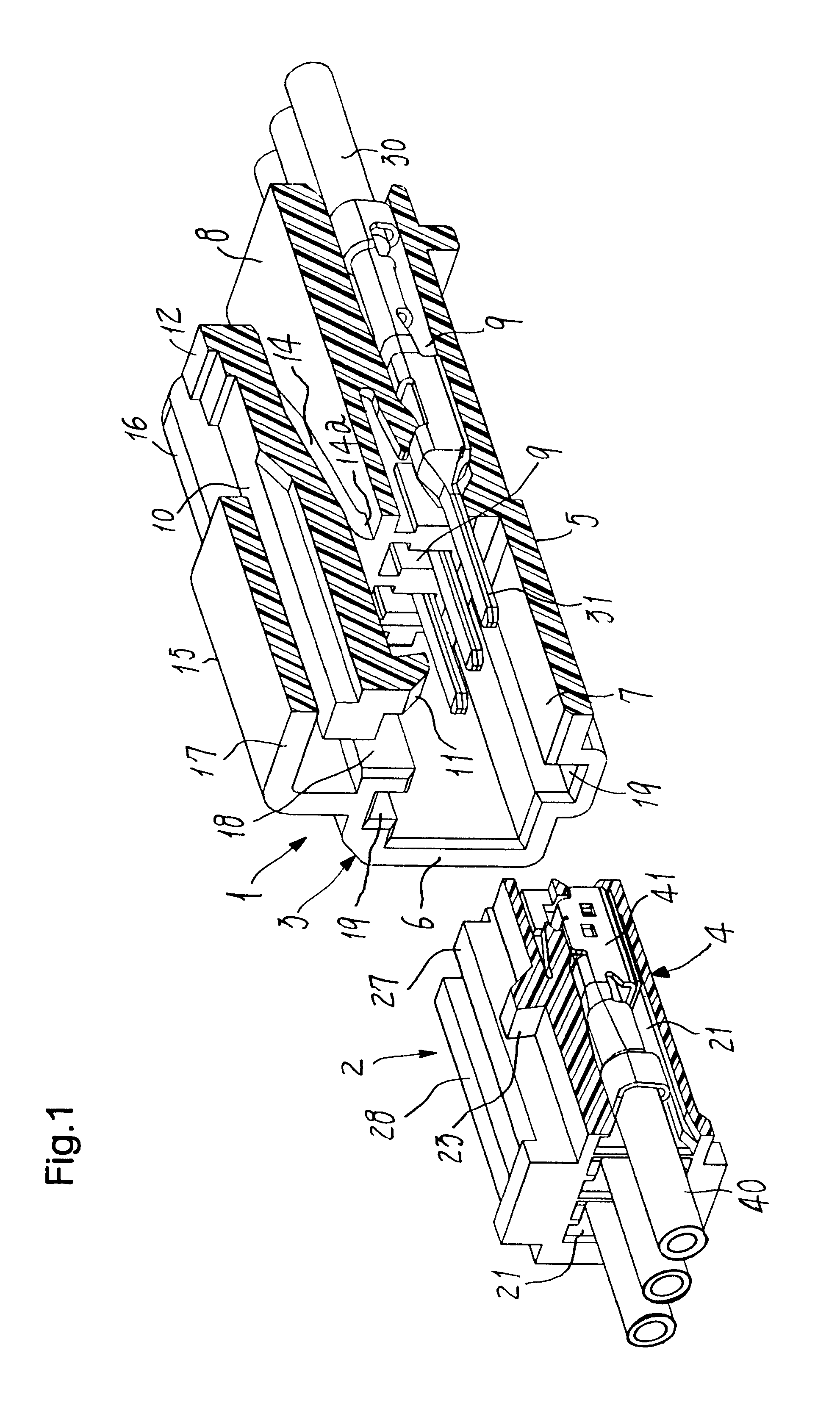
FIG. 1 shows a connector assembly having a latching mechanism provided herein. A plurality of wire ends 30 are electrically connected to another plurality of wire ends 40 by the present connector assembly that is exemplified herein as of the relay or junction type. This assembly is composed of a male connector 1 and a female connector 2 fitting therein. The male connector 1 comprises a housing (hereinafter referred to as `male housing`) 3, and the female connector 2 comprises another housing (hereinafter referred to as `female housing`) 4, both the housings being made of an insulating resin such as Nylon (a registered trademark).

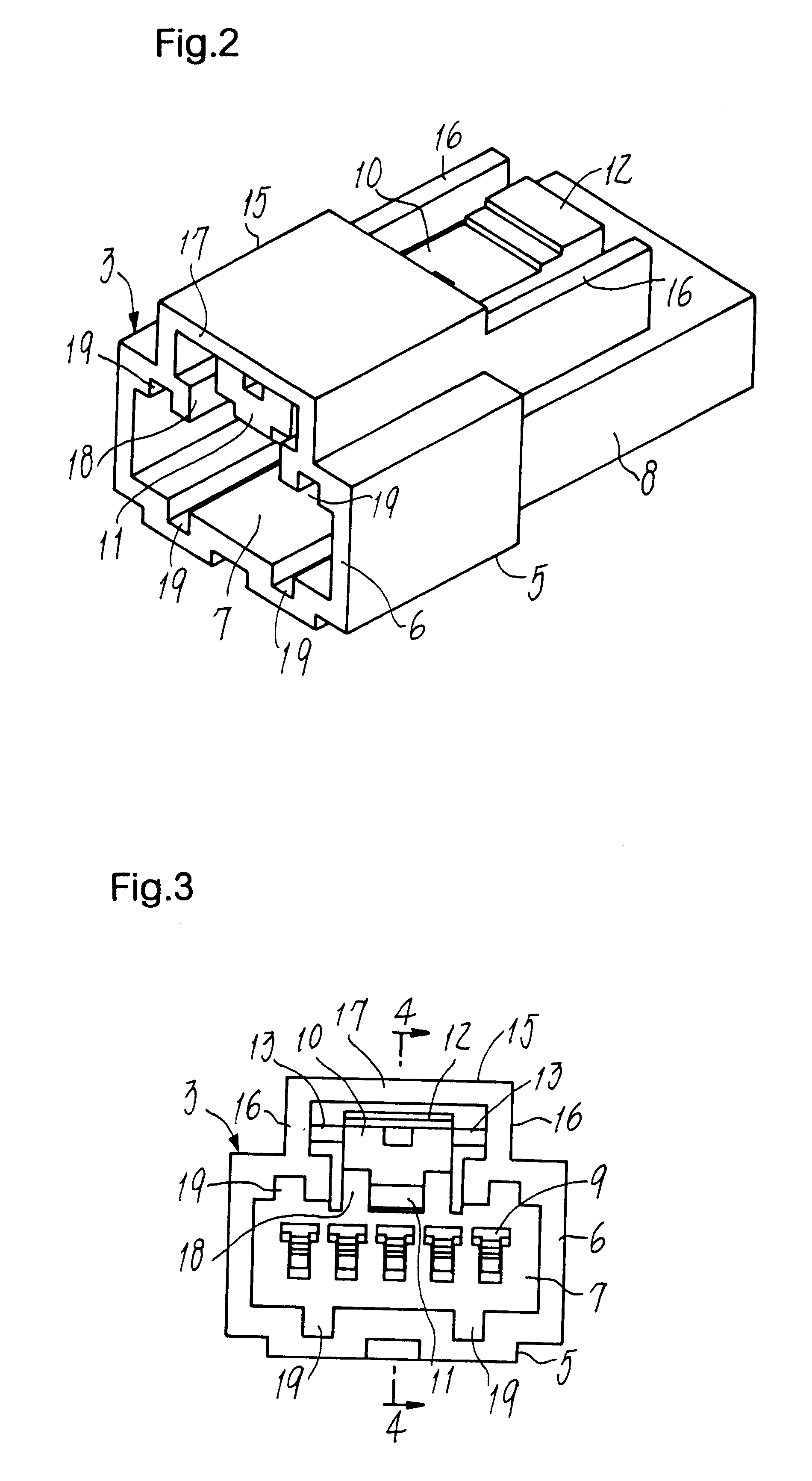
As shown in FIGS. 2 to 5, a main body 5 of the male housing 3 consists of a generally square cylinder 6 having a cavity 7 opened forwards and a flat and elongate parallelepiped box 8 formed integral with the square cylinder 6. A plurality of pin contacts 31 (see FIG. 1)...


PUM


Abstract

A connector assembly has a male connector (1) engaging with a female connector (2), and a latching mechanism is composed of a lockable lug (23) formed on a female housing (4) and a lock arm (10) formed on a male housing (3). Elastically deforming hinge-shaped feet (13) have each one end integral with the male housing and the other end continuing from the lock arm, whose pawl (11) corresponds to the lug (23), so that the lock arm (10) rocks about the feet to engage the pawl with the lug. A push lever (12) has lateral ends integral with the lock arm's rear end disposed in rear of the feet (13). A supplementary resilient arm (14) continues from the rear end to be inclined down and forwards. Its fore end is fixed on the outer surface of male housing (3), such that the housings are firmly locked together to give a stronger "click' feeling for detection of engagement, with wire ends from any foreign harness never catching the push lever.

Description

1. Field of the InventionThe present invention relates to a connector assembly composed of a pair of male and female connectors mating one another and having a latching mechanism, wherein the male connector fits in the female connector to establish an electric communication between them.2. Prior ArtMany connector assemblies each comprising a latching mechanism of this type have been known in the art. In each assembly having the latching or interlocking mechanism which the present invention addresses, one connector housing (viz., a first housing) has a lockable lug formed on the outer surface thereof. The other connector housing (viz., a second housing) has a lock arm formed integral with a pawl capable of engaging with the lockable lug. Elastically deformable hinge-shaped feet formed on the second housing serve to releasably secure the lock arm to the outer surface of second housing. The second housing has also a push lever formed on the rear end of the lock arm, to be disposed rear...

Claims


Application Information

Patent Timeline
Patent Type & Authority Patents(United States)
IPC IPC(8): H01R13/627H01R13/639H01R13/629H01R13/64
CPCH01R13/6272H01R13/629
Inventor CHEN, PING
Owner JST MFG CO LTD
Why Eureka
Try Eureka