Combination lock system

a combination lock and lock technology, applied in the direction of mechanical control devices, keyhole guards, restricting/preventing/returning movement of parts, etc., can solve the problems of difficult time-consuming, large number of coders used in this kind of coded combination lock system, and inability to code. the effect of further simplifying the coding operation

Inactive Publication Date: 2003-06-10
UNITECHN
View PDF9 Cites 22 Cited by
  • Summary
  • Abstract
  • Description
  • Claims
  • Application Information

AI Technical Summary

Benefits of technology

The present invention applies to this type of coded combination lock and aims to simplify further the coding operation.
Accordingly, actuating a push-button that is part of the combination and actuating a push-button that is not part of the combination have exactly the same subjective effect, so the user cannot detect any difference, in particular any tactile or audible difference, between actuating the two push-buttons.
In this type of lock, unlocking is possible when all the coders have locking markers disposed in a corresponding relationship, generally aligned with each other. In their waiting position, the coders selected for the combination are offset relative to the inactive coders. The offset is such that, if the selected coders are moved to the unlocking position, the second unlocking markers of the selected coders come into corresponding relationship with the first unlocking markers of the unselected coders, which have remained in the inactive position. Accordingly, even in the unlocked position, the selected coders are offset relative to the unselected coders. This facilitates resetting, which consists of returning the coders to the waiting position after actuation of the push-buttons. This is because, at the time of a reset, the selected coders which are in the unlocking position are selectively moved to the coding position and any unselected coders that may happen to be in the locking position are returned to the inactive position.
In this case, it is advantageous if each coder has spaced first and second actuation surfaces respectively adapted to cooperate with a push-button in order, when the push-button is depressed, to cause the coder to be moved between its inactive position and its locking position and between its coding position and its unlocking position.
It is also advantageous if each coder has spaced first and second reset surfaces and the means for returning the coders to the waiting configuration after the push-buttons are actuated comprise a reset member adapted to co-operate with the first reset surfaces of the coders occupying the locking positions to return said coders to their inactive positions and to co-operate with the second reset surfaces of the coders occupying their unlocking positions to return said coders to their coding positions.

Problems solved by technology

Moving a coder in the "right" rotation direction unlocks the lock, which is not possible if a coder is moved in the "wrong" rotation direction.
The number of coders used in this kind of coded combination lock system can be very large.
Coding the combination necessitates putting all these coders in a correct position relative to each other, which, given their number, is difficult and time-consuming.
There is therefore a risk that the code can eventually be detected.

Method used


Image

  • Combination lock system
  • Combination lock system
  • Combination lock system

Examples


Embodiment Construction

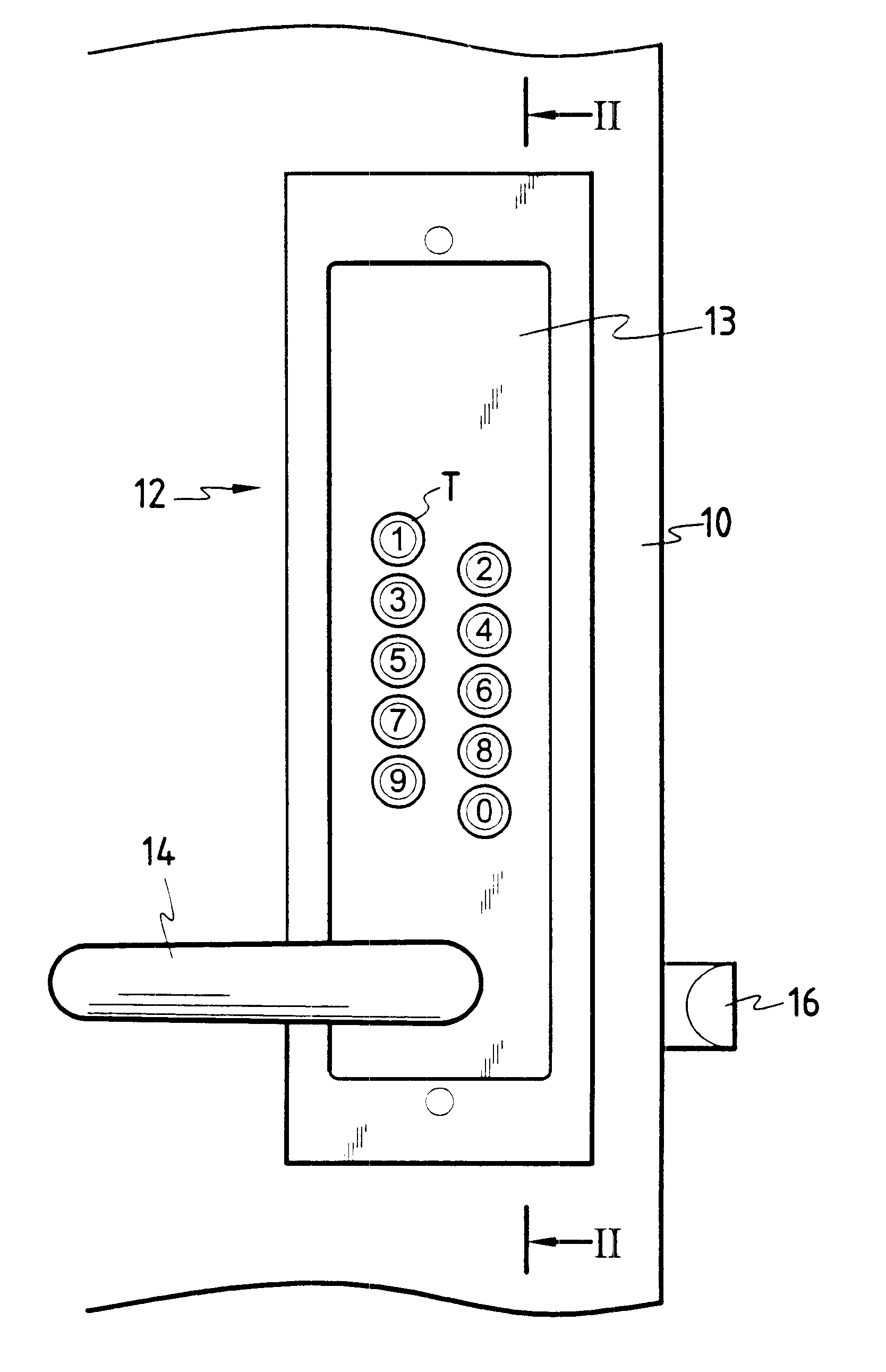
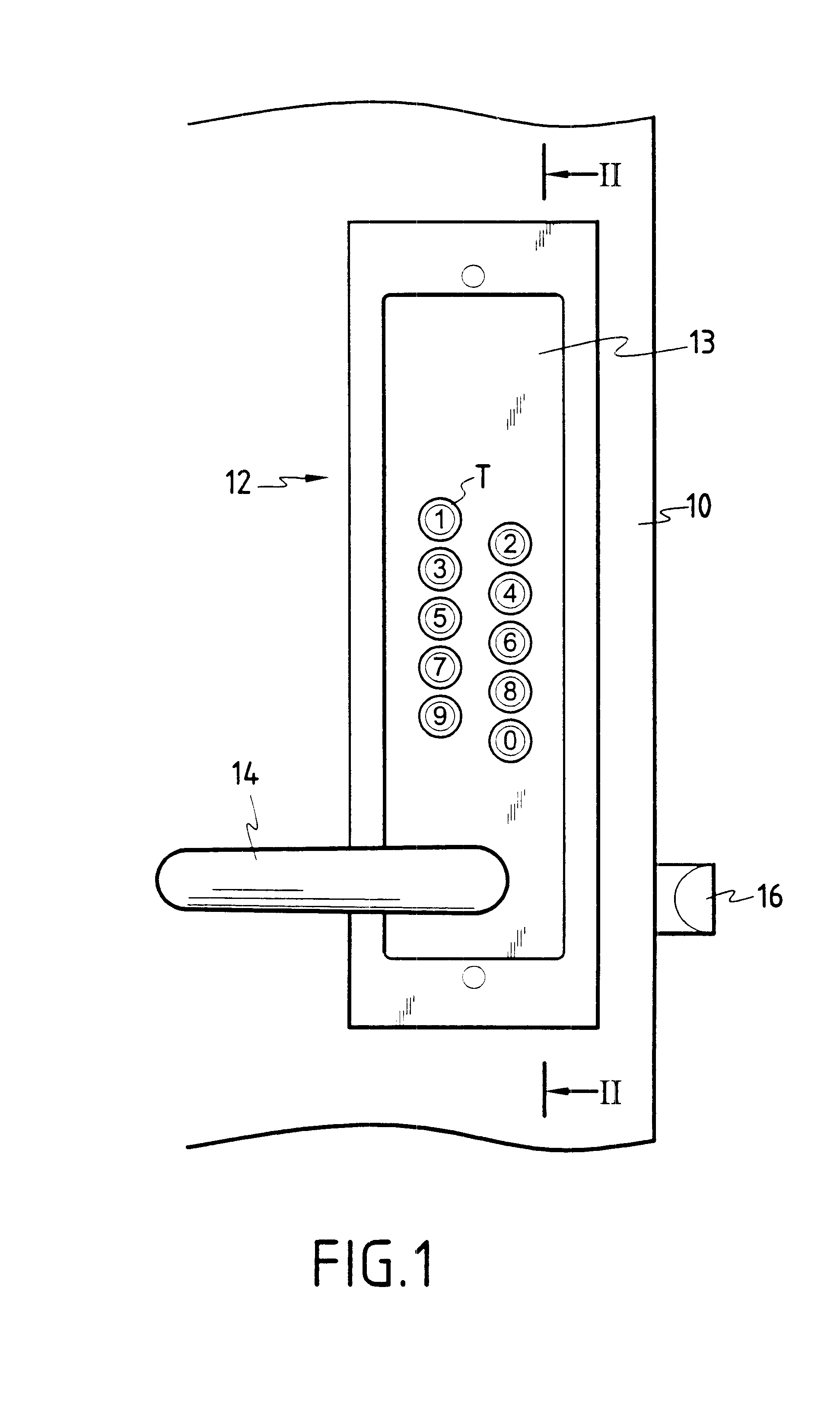
Referring to FIG. 1, a door 10 is equipped with a combination lock system 12 according to the invention which comprises a set of push-buttons T disposed on a panel on the outside of the door. In this example there are ten numeric push-buttons arranged as two rows each of five push-buttons. If the correct combination is entered by manipulating the push-buttons, locking means of the lock, such as a bolt 16, can be opened by actuating a door handle 14.

The lock is installed on the outside face of a door, whose inside face is the opposite face. The outward direction is that from the inside face towards the outside face. In the conventional way, the two rows of push-buttons are oriented vertically and the longitudinal direction of the lock system, to which the transverse direction is perpendicular, is the vertical direction.

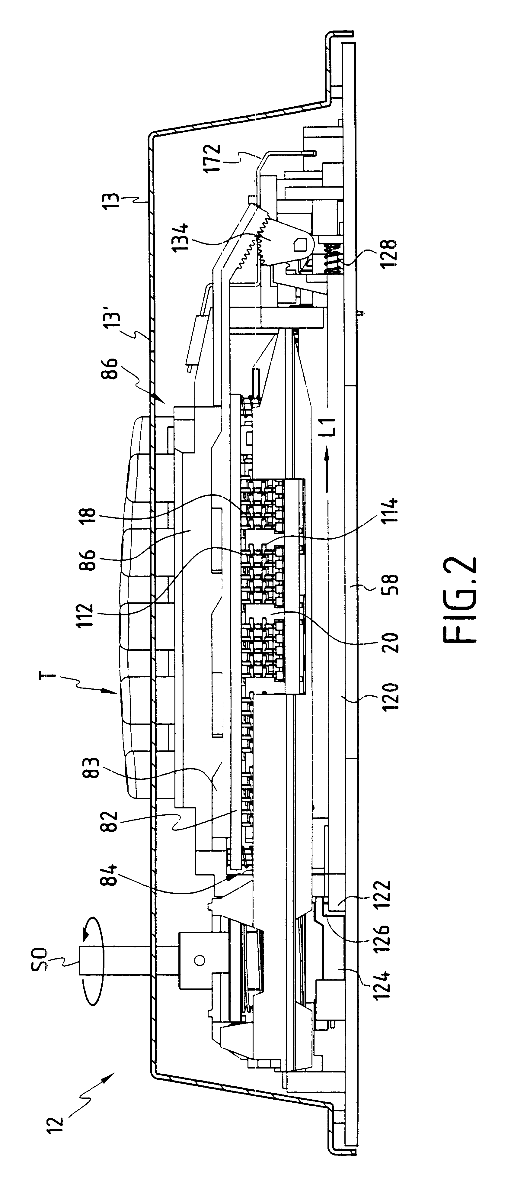
The section plane of FIG. 2 is aligned with one side of the casing 13 of the lock system and this sectional view shows internal components of the system. FIG. 3 also s...


PUM


Abstract

A combination lock system comprising a set of push-buttons, a set of series of coders each of which series is associated with a push-button, incrementing means for placing the coders of each series successively in a position to be operated by a push-button, coding means for selecting some coders and placing them in a coding position, and means for returning the coders to a waiting configuration after the push-buttons are actuated. The system comprises means for authorizing two actuation strokes of the push-buttons, namely a normal stroke commanding movement of a coder which is part of the code between its coding position and an unlocking position and a coding travel moving a coder from its inactive position to its coding position. For entering a new coded combination, the system further comprises means for placing all the coders in the inactive position and authorizing actuation of the push-buttons over the coding stroke.

Description

The present invention relates to a combination lock system comprising a set of push-buttons that can be actuated in compliance with a combination, a set of series of coders, in which each series is associated with a push-button, incrementing means for placing the coders of each series successively in a position to be operated by actuating a push-button, coding means for defining a waiting configuration of the coders in which the coders selected for the combination occupy a coding position and the coders not selected for the combination occupy an inactive position, actuation of the locking means of the lock being possible if the selected coders have been operated by actuating push-buttons in compliance with the combination, the system further comprising means for returning the coders to the waiting configuration after actuation of the push-buttons.Each push-button is associated with a series of several coders, for example four or five coders. In a waiting position, each first coder o...

Claims


Application Information

Patent Timeline
Patent Type & Authority Patents(United States)
IPC IPC(8): E05B37/00E05B37/16
CPCE05B37/163Y10T70/7311Y10T70/7266Y10T70/726Y10T70/7282Y10T70/7305Y10T70/5788Y10T70/7271
Inventor BERTON, CYRILCHERIOT, GERARD
Owner UNITECHN
Why Eureka
Try Eureka