Directly actuated injection valve

a technology of injection valve and actuator, which is applied in the direction of fuel injection pumps, machines/engines, electric control, etc., can solve the problems of high fuel pressure within and high pressure in the injection valve or injector, so as to reduce the load, reduce the wear of the valve seat, and reduce the effect of injection

Inactive Publication Date: 2003-06-10
WESTPORT FUEL SYST CANADA INC
View PDF22 Cites 67 Cited by
  • Summary
  • Abstract
  • Description
  • Claims
  • Application Information

AI Technical Summary

Benefits of technology

Dashed line D shows that the shape of the waveform can be manipulated to influence the movement of the valve member. In this example the current is momentarily made negative to I.sub.4 to accelerate the valve closing and then made momentarily positive again to I.sub.5 to slow down the valve member to reduce impact and wear on the valve member and valve seat. The current could also be kept positive (that is I.sub.4 equals zero) and current could be momentarily raised to I.sub.5 to slow down the valve member before it contacts the valve seat. Dashed line E also shows that valve closing impact and wear to the valve seat and valve member can be reduced by slowing the rate at which the current is reduced to zero.
By shaping the control pulse waveform applied to the actuator it is possible to slow down the closing of the injection valve to reduce impact on the valve member and the valve seat.

Problems solved by technology

Direct injection at high pressures presents several challenges.
The use of high-pressure fuels for direct injection results in high fuel pressures existing within the injection valve or injector.
Moreover, compared to low-pressure systems, higher forces are needed to open or close the injection valve.
For example, for a needle valve that employs an inwardly opening valve needle, when the needle is in the open position it may be subjected to high forces from the pressurized fuel.
Conversely, with an outward opening injection valve, a high amount of force is required to keep the valve closed against the high fuel pressure within the injection valve body.
Additionally, there is only a small window of time during which the fuel can be injected.
However, in the context of a conventional gaseous injection valve, hydraulic operation presents several drawbacks, including:
increased bulkiness of the injection valve assembly because of the additional hardware requirements; and
delayed response of the system caused by time delays associated with the dynamic flow of the hydraulic fluid, the actuation of the electronic hydraulic valve hardware and the movement of the needle that controls gas flow from the injection valve.
Moreover, the degree of controllability of the movement of the injection valve is low when the motive force is provided by a pressurized fluid rather than by a directly controllable source.
In this respect, it is difficult to control lift, resulting in limited lift control capabilities when using hydraulically actuated injection valve with a double-spring configuration.
A problem with employing a piezoelectric or magnetostrictive actuator to operate a control valve, which in turn controls the flow of a hydraulic fluid to operate an injection valve, is that this arrangement requires the intermediate action of a hydraulic fluid.
Any delays caused by the displacement of the hydraulic fluid causes delays in the actuation of the injector.
Another disadvantage of active hydraulically operated systems is that a hydraulic fluid needs to be supplied and drained from a hydraulic cylinder.
A disadvantage of active hydraulic actuators of this type is that there is a lag time associated with moving the hydraulic fluid into and out of the hydraulic cylinder.
However, those skilled in the technology involved here will recognize that the figures are not construction drawings and are not drawn to scale.
However, the amount of displacement may decline as a function of increasing temperature.

Method used


Image

  • Directly actuated injection valve
  • Directly actuated injection valve
  • Directly actuated injection valve

Examples


Embodiment Construction

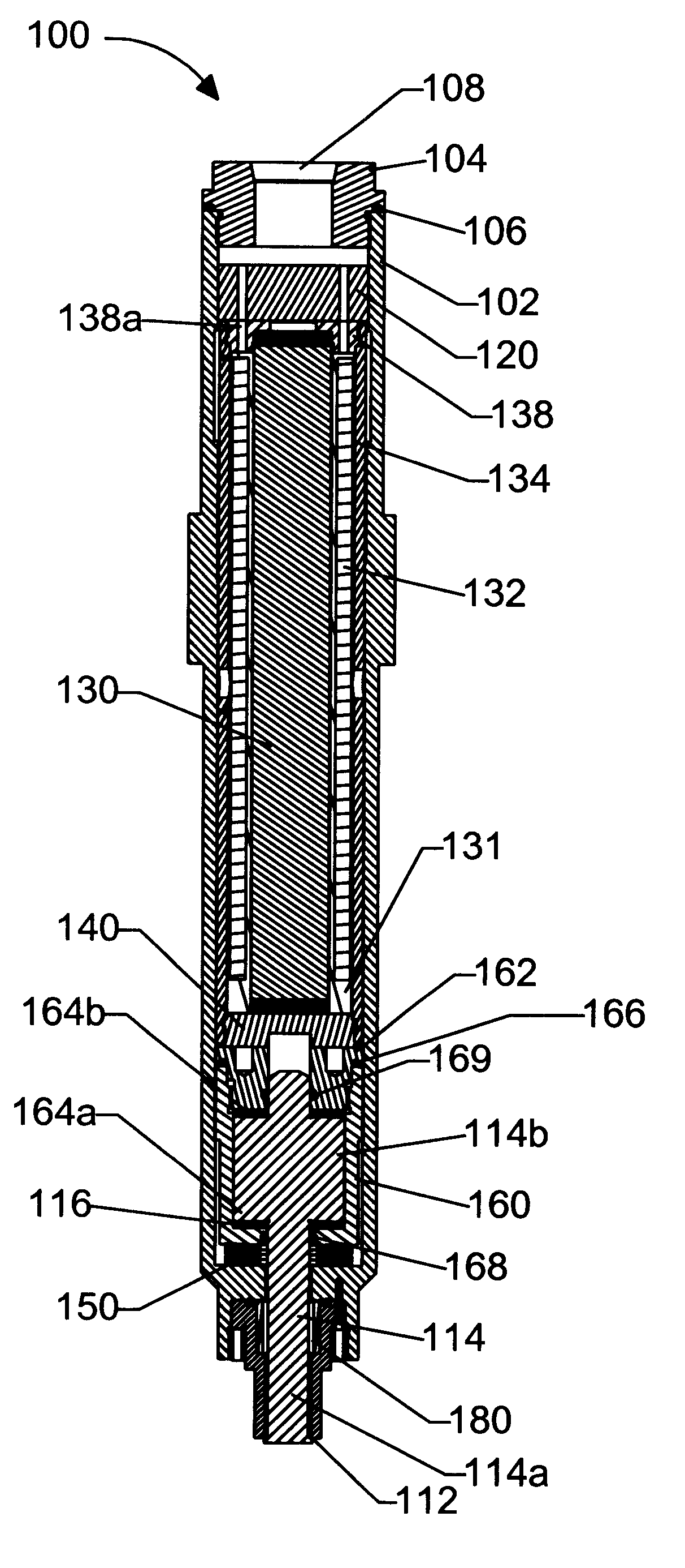
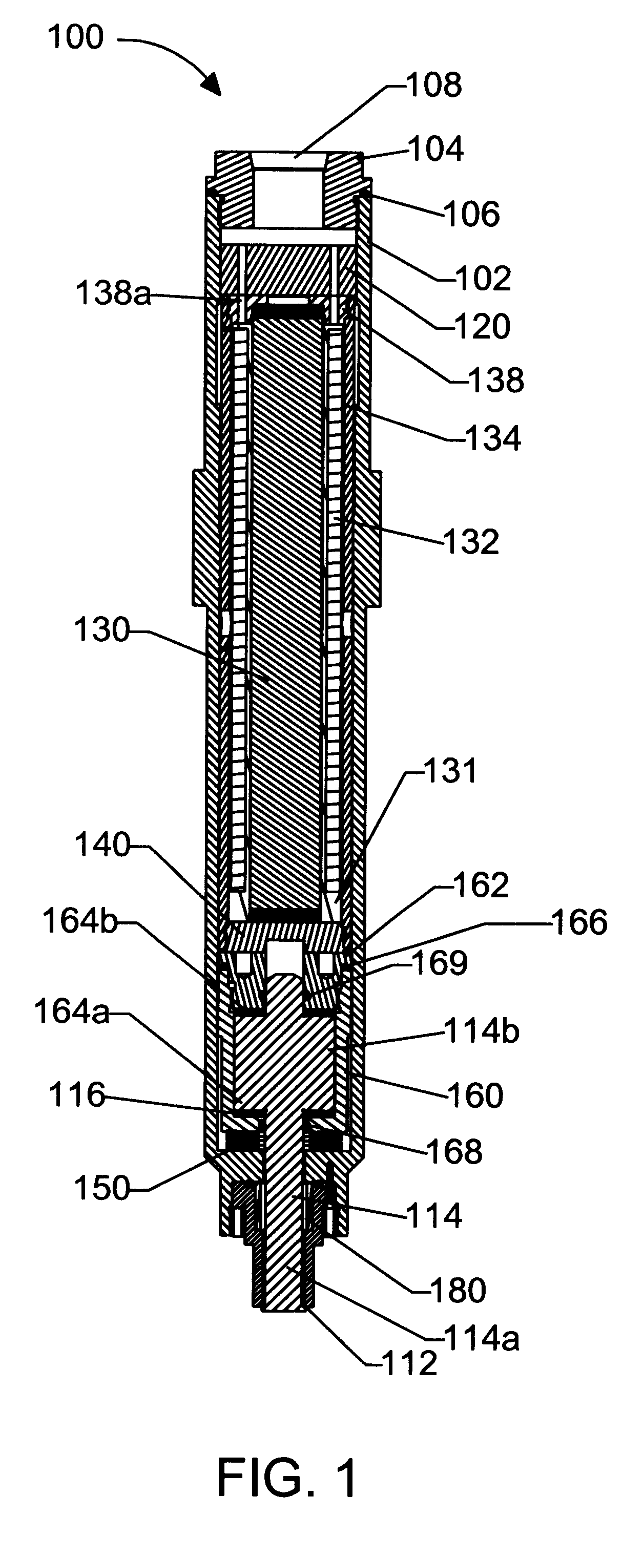
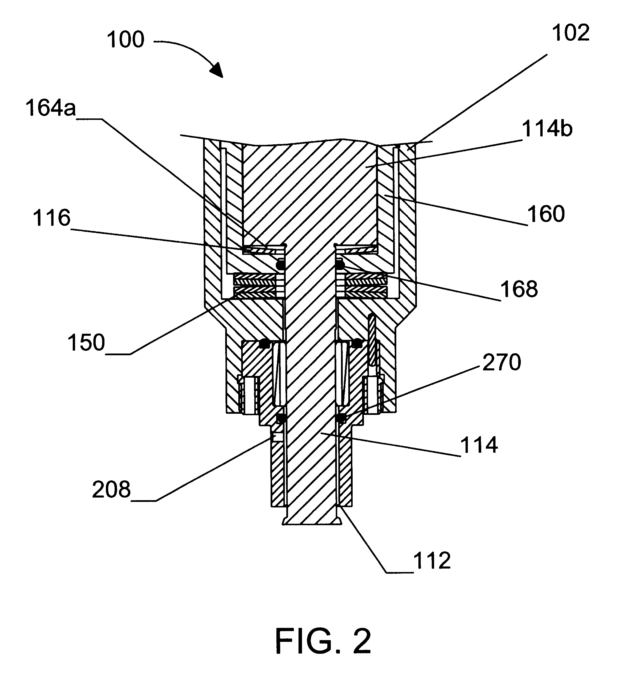
FIGS. 1 and 3 show two different preferred embodiments of an outward opening directly actuated fuel injection valve for internal combustion engines. Opposed to a needle valve, which employs a needle that is retracted into the valve body to open the valve, an outward opening injection valve extends a valve member outward and away from the valve body to open the valve. To open an outward opening fuel injection valve for injecting fuel into an engine, a valve member is moved away from a valve seat and towards the combustion chamber.

Referring to FIGS. 1 and 2, injection valve 100 includes elongated valve housing 102 that cooperates with valve cap 104 to provide a fluidly sealed valve body. Seal 106 may be employed to ensure that the assembled valve body is fluid-tight. Valve cap 104 comprises inlet port 108 through which fuel enters the valve body. Valve housing 102 further comprises valve seat 112, which is better shown in FIG. 2, which shows an injection valve in the open position.

The...


PUM


Abstract

A directly actuated injection valve comprises a hollow valve housing, a valve member disposed within the hollow interior, a biasing mechanism, an actuator assembly and a passive hydraulic link assembly. The valve member is movable between a closed position and an open position for governing the flow of fuel into the combustion chamber of an internal combustion engine. The biasing mechanism, preferably a spring, biases the valve member in the closed position. The actuator assembly generates an opening force that acts against the valve spring to open the valve. The hydraulic link assembly is interposed between the valve member and the valve spring and the actuator assembly. The hydraulic link assembly transmits respective closing and opening forces to the valve member. The hydraulic link preferably comprises a piston disposed within a cylinder that is filled with a hydraulic fluid.

Description

The present invention relates generally to high pressure fuel injection valves or injectors for internal combustion engines, and, more specifically, to an injection valve that is directly controllable by a position actuating material (such as, for example, a piezoelectric or magnetostrictive material) and which includes a passive hydraulic link.Direct injection of a gaseous fuel into the combustion chamber of an internal combustion engine is desirable for several reasons. For example, direct injection allows charge stratification, eliminating throttling losses associated with homogeneous charge engines. Additionally, with direct injection late in the compression stroke, a high-compression ratio can be maintained, maintaining efficiency. Further, when the fuel that is directly injected comprises natural gas, propane, or hydrogen, the emissions of NO.sub.x and particulate matter (PM) are significantly reduced. The directly injected gaseous fuel can be ignited with a glow plug, with a ...

Claims


Application Information

Patent Timeline
Patent Type & Authority Patents(United States)
IPC IPC(8): F02M61/16F02M61/08F02D41/20F02M61/00F02M61/10F02M21/02F02M51/06F02M51/00F02M63/00F02M47/00F02M47/04
CPCF02M21/0254F02M51/005F02M51/0603F02M51/0607F02M61/08F02M61/10F02M61/166F02M61/167F02M21/0269F02D41/20F02B2275/14F02D41/2096F02D2041/2037F02M2200/30F02M2200/304F02M2200/507Y02T10/123Y02T10/32Y02T10/12Y02T10/30
Inventor WELCH, ALAN B.RAHARDJA, IRAWANHEBBES, MIKE
Owner WESTPORT FUEL SYST CANADA INC
Why Eureka
Try Eureka