
Light system for battery powered drill

a battery-powered drill and light system technology, applied in the field of battery-powered drills, can solve the problems of general limited positioning of stand-alone lights, and achieve the effect of simple and economic manufactur

Inactive Publication Date: 2003-06-10
WADSWORTH JAKE
View PDF5 Cites 65 Cited by
  • Summary
  • Abstract
  • Description
  • Claims
  • Application Information

AI Technical Summary

Benefits of technology

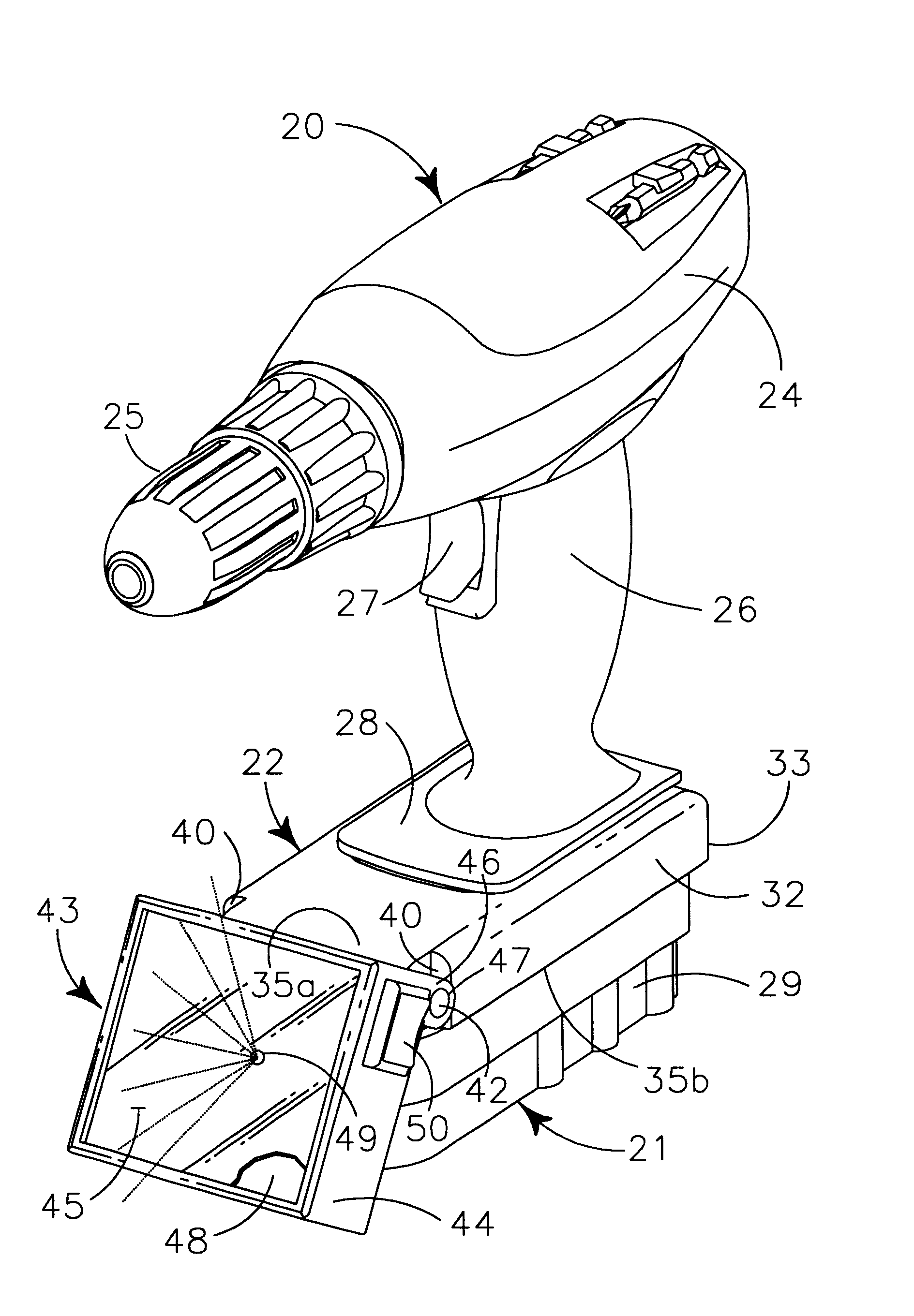
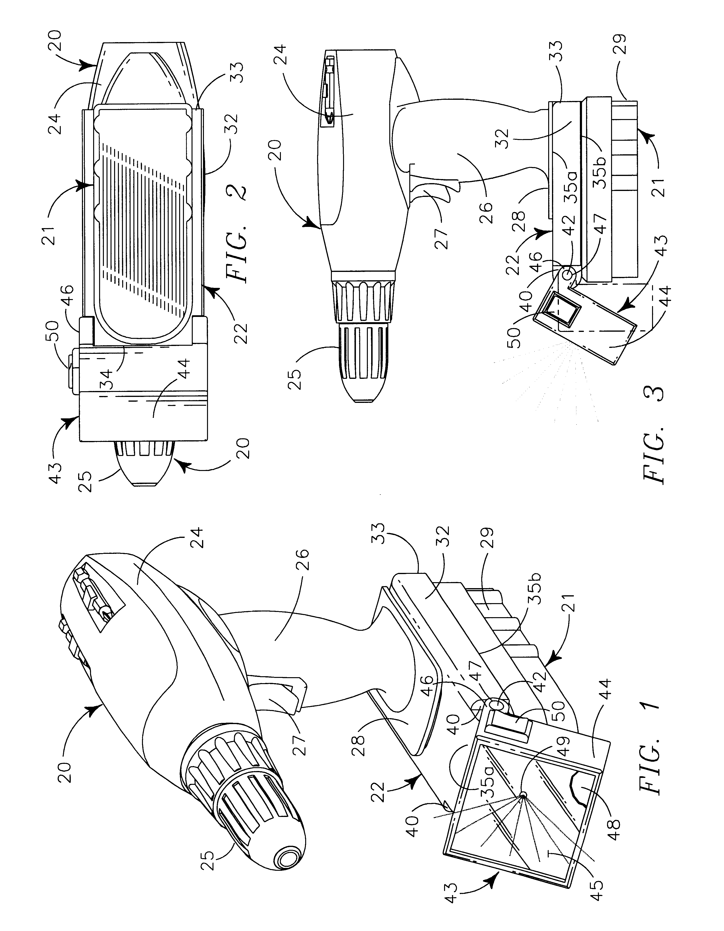
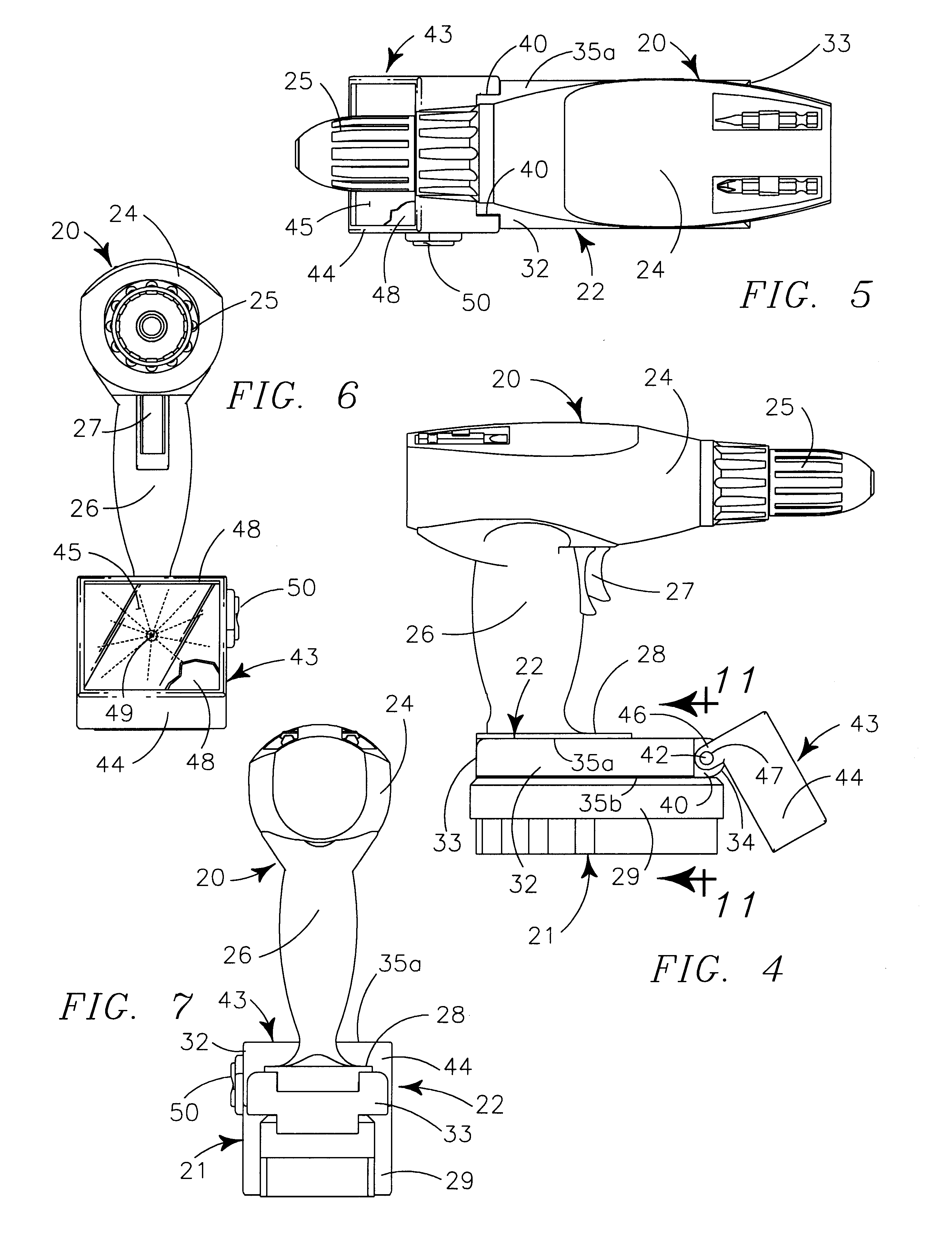
My invention generally provides a light structure for use with battery powered electric drills having a depending handle releasably carrying a removable battery therebeneath. The light structure has a lower connecting portion configured to releasably interconnect with the existing connecting structure of the battery and an upper connecting structure configuration to releasably interconnect with the existing connecting structure of the powered drill. The light structure provides a pivotally interconnected light source at the forward end to pivot in a vertical plane relatively to the vertically positioned drill to adjustably illuminate an area about that whereat a drill bit operates. An interconnectable handle structure provides a base having lower connecting structure configured to releasably interconnect the connecting structure defined by the upper portion of the light structure to aid manual manipulation and support of the light structure and an interconnected drill battery to serve as a stand alone light. The handle body pivotally carries an L-shape handle formed by two pivotally interconnected elongate elements to provide a wide range of support positions for the stand-alone light mode of the light structure on an underlying supporting surface.
A still further object is to provide such a handle that is formed by two pivotally interconnected elongate elements for pivotal motion in the same vertical plane as the pivotal motion of the handle to aid adjustable positioning of the light structure on an underlying supporting surface.
A still further object is to provide such a light structure that is of new and novel design, of a rugged and durable nature, of simple and economic manufacture and one that is otherwise well-suited to the uses and purposes for which it is intended.

Problems solved by technology

The stand alone light's positioning is generally limited only by an operator's ingenuity in relatively positioning the elements of the light structure for support.

Method used


Image

  • Light system for battery powered drill
  • Light system for battery powered drill
  • Light system for battery powered drill

Examples


Embodiment Construction

The instant light system is created for use with a cordless battery powered electric drill 20. A representative generic form of such a drill with which the light system is operative is illustrated particularly in FIGS. 1-7, where it is seen to provide elongate drill body 24 carrying a drill motor (not illustrated) powering rotatable chuck 25 in its forward end portion to releasably carry and positionally maintain tool bits. Elongate handle 26 depends from the medial portion of body 24 and carries finger switch 27 in the forward portion of the handle 26 immediately beneath the junction of the handle with body 24. The lowermost portion of handle 26 supports battery connecting structure 28, which without use of my light system, normally releasably interconnects, both structurally and electrically, battery casement, 29 carrying a powering battery (not illustrated).

As seen in the expanded view of FIG. 9, battery connecting structure 28 of the drill 20 and battery casement 29 each define ...


PUM


Abstract

A light structure releasably interconnects between a battery powered drill and the powering battery to provide a drill light in a first mode and in a second mode releasably interconnects the powering battery therebelow and a handle structure thereabove to serve to as a stand alone light independent of the drill. The light structure pivotally carries a light source for vertically angulated positioning. The handle structure provides a pivotally interconnected L-shaped handle formed by two adjustably pivotally interconnected elongate elements to allow adjustable positioning of the light structure relative to an underlying supporting surface.

Description

II. BACKGROUND OF INVENTIONIIA. Related ApplicationsThere are no applications related hereto heretofore filed in this or in any foreign country.IIB. Field of InventionThis invention relates generally to battery powered drills and more particularly to a light structure releasably attachable between the drill as its powering battery that has a releasably attachable handle to allow use as a stand alone light independent of the drill when powered by the drill battery.IIC. Background and Description of Prior ArtWith the advent of present day rechargeable batteries of relatively small size and long life that provide substantial power for longer periods between chargings, cordless battery powering has become popular for the operation of smaller hand tools. This has been especially true in the case of drills, which by their nature and use are well suited for powering by battery means. Often battery powered tools such as drills are used in poorly lighted areas, commonly more often than their...

Claims


Application Information

Patent Timeline
Patent Type & Authority Patents(United States)
CPCB25B21/00B25F5/021B25B23/18
Inventor WADSWORTH, JAKE
Owner WADSWORTH JAKE
Learn More