Method and system for controlling a light source

a technology for controlling a light source and a control method, which is applied in the direction of optical radiation measurement, instruments, spectrometry/spectrophotometry/monochromators, etc., can solve the problems of extremely difficult and expensive manufacturing of sensors, and commercially unfeasible problems

Inactive Publication Date: 2003-06-10
KONINK PHILIPS ELECTRONICS NV
View PDF10 Cites 119 Cited by
  • Summary
  • Abstract
  • Description
  • Claims
  • Application Information

AI Technical Summary

Problems solved by technology

However, such sensors are extremely difficult and very expensive to manufacture, and are therefore commercially unfeasible.

Method used


Image

  • Method and system for controlling a light source
  • Method and system for controlling a light source
  • Method and system for controlling a light source

Examples


Embodiment Construction

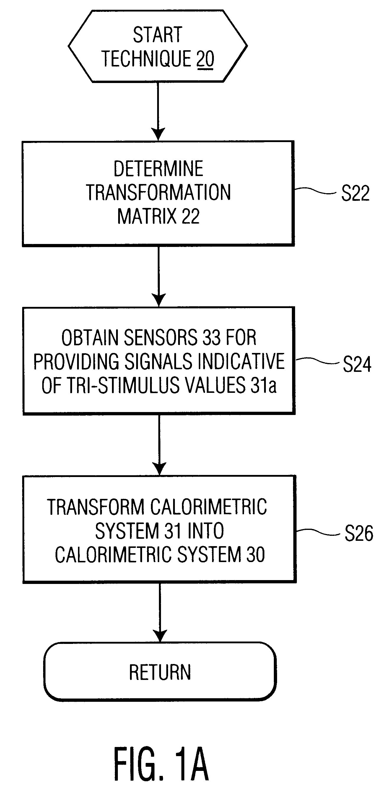
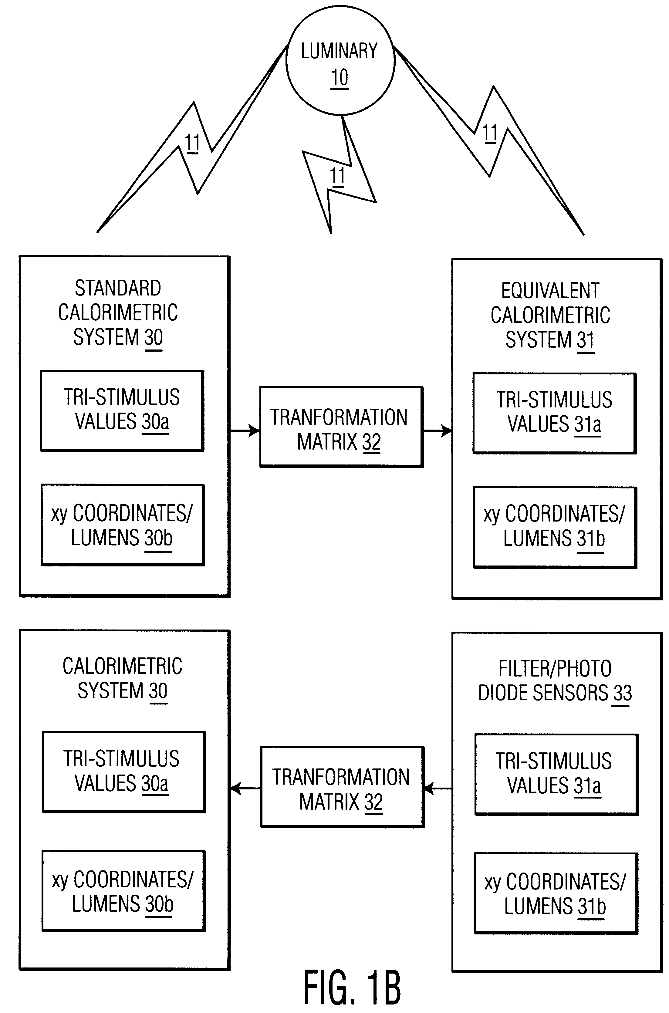
FIG. 1A illustrates a transformation technique 20 in accordance with the present invention, and FIG. 1B illustrates the principles of technique 20.

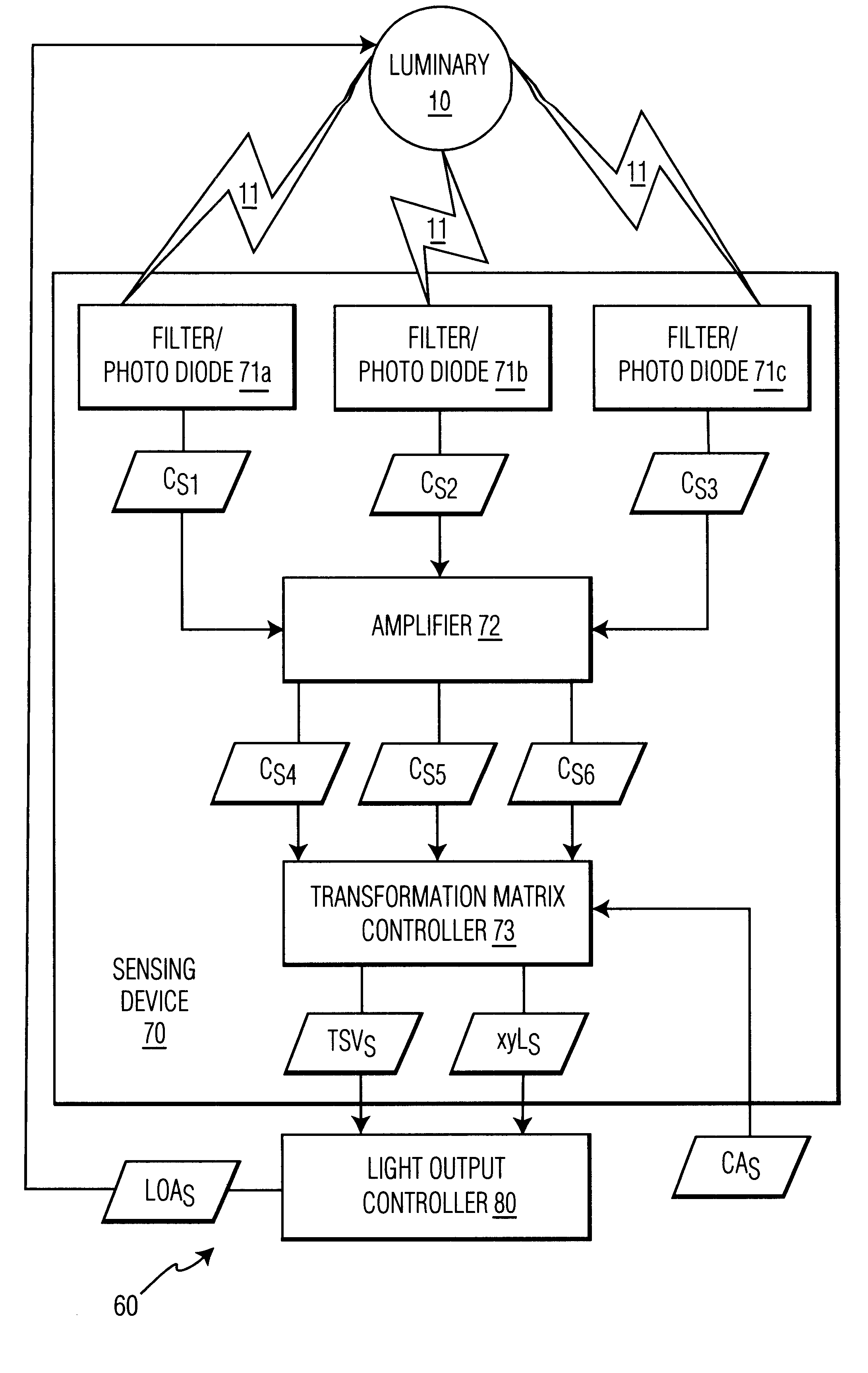
Referring to FIGS. 1A and 1B, manufacturing conventional filter / photo diode sensors 33 to match the color matching functions of a standard calorimetric system 30 for a given accuracy is difficult and therefore, such filter / photo diode sensors 33 are not commercially available to directly sense the tri-stimulus and chromaticity coordinates of a standard calorimetric system. Transformation technique 20 overcomes this problem. During a stage S22 of technique 20, a transformation matrix 22 for transforming standard calorimetric system 30 into an equivalent calorimetric system 31 having color matching functions that can be used to sense by some, if not all, conventional filter / photo diode sensors 33.

In one embodiment, calorimetric system 30 is a Commission International de l'Eclairage (CIE) color measurement system expressed in terms of color ...


PUM


Abstract

A light output control system for implementing a method for sensing the tri-stimulus values for controlling a light output illuminated from an LED based luminary is disclosed. The system comprises one or more filter / photo diode sensors for sensing a first set of tri-stimulus values of the light output and providing signals indicative thereof. The signals are utilized in a transformation matrix whereby a second set of tri-stimulus values is obtained. The system controls the light output as a function of the second set of tri-stimulus values.

Description

1. Field of the InventionThe present invention generally relates to controlling a luminary. The present invention specifically relates to sensing tri-stimulus values for a feedback control of a light output illuminating from a luminary including a plurality of light emitting diodes (LEDs) illuminating various colors of light.2. Description of the Related ArtWhite light generation based on a Red LED, Green LED, and Blue LED (RGB LED) is well known in the art. It is also known that, even when produced from the same fabrication process, the optical characteristics of individual RGB LED can significantly vary in a batch. In addition, the characteristics of the LEDs vary with the forward current, ambient temperature, and aging. As a result, the quality of white light produced by each individual RGB LED based luminary will vary. Thus, to minimize, if not to eliminate, the quality variance of white light produced by a RGB LED based luminary, a feedback control system is required to establi...

Claims


Application Information

Patent Timeline
Patent Type & Authority Patents(United States)
IPC IPC(8): H05B33/02H05B33/08H05B44/00H05B37/02
CPCH05B33/0869H05B33/086H05B45/22H05B45/20
Inventor MUTHU, SUBRAMANIANVAN DER SIJDE, ARJEN
Owner KONINK PHILIPS ELECTRONICS NV
Why Eureka
Try Eureka