
Front end panel

a front end panel and intake duct technology, applied in the direction of superstructure subunits, propulsion parts, vehicle components, etc., can solve the problems of difficult to reduce the manufacturing cost of the vehicle, difficult to incorporate an air cleaner box, and difficult to reduce assembly tim

Inactive Publication Date: 2003-06-17
DENSO CORP
View PDF17 Cites 32 Cited by
  • Summary
  • Abstract
  • Description
  • Claims
  • Application Information

AI Technical Summary

Benefits of technology

In view of the above points, it is a first object of the present invention to reduce the time required to assemble an intake duct.
In view of the above points, it is a second object of the present invention to effectively utilize a space in an engine compartment while an increase in the size of the front end panel is prevented.
Due to the foregoing, when the front end panel is incorporated into a vehicle under the condition that the duct member is assembled onto the front panel, assembling the intake duct is completed. Accordingly, it is possible to reduce the time required to assemble the intake duct. Therefore, the manufacturing cost of the vehicle can be decreased.
Accordingly, it is unnecessary to arrange an air rough mesh filter, for removing large foreign objects such as rain water and snow, in the air path. Therefore, it is unnecessary to increase the volume of the intake duct. Consequently, when the intake duct capable of removing foreign objects is formed on the front end panel while an increase in the size of the front end panel is being prevented, it is possible to effectively utilize a space in the engine compartment.

Problems solved by technology

Therefore, it is difficult to reduce the time of assembly.
Accordingly, it is difficult to decrease the manufacturing cost of the vehicle.
Accordingly, it is difficult to incorporate an air cleaner box, the volume of which is sufficient to accommodate the air filter, onto the front end panel.
Therefore, the front end panel, the structure of which is the same as that disclosed in the above patent publication, is difficult to put into practical use.
Therefore, it is unnecessary to increase the volume of the intake duct.

Method used


Image

  • Front end panel
  • Front end panel
  • Front end panel

Examples


Embodiment Construction

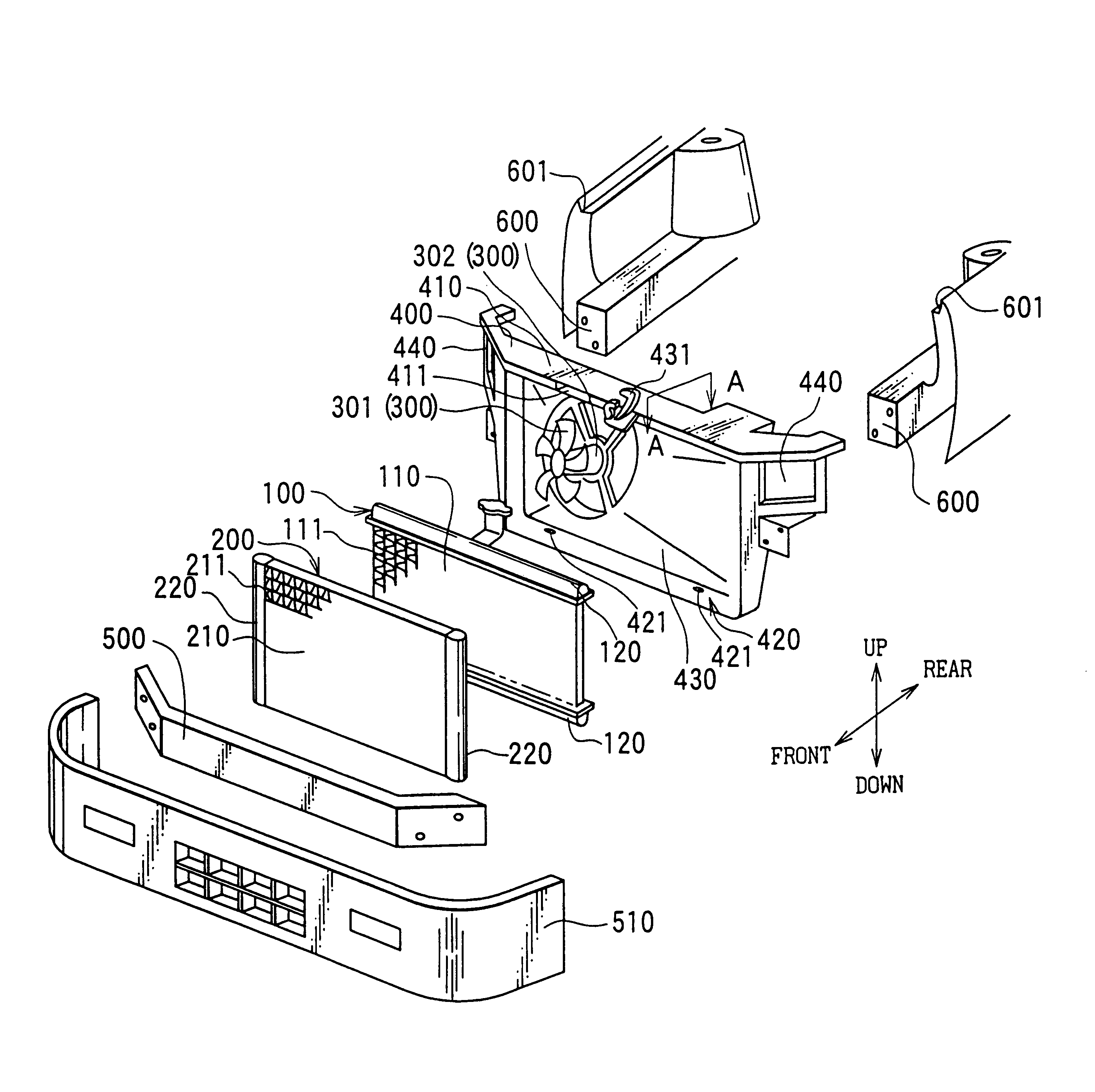
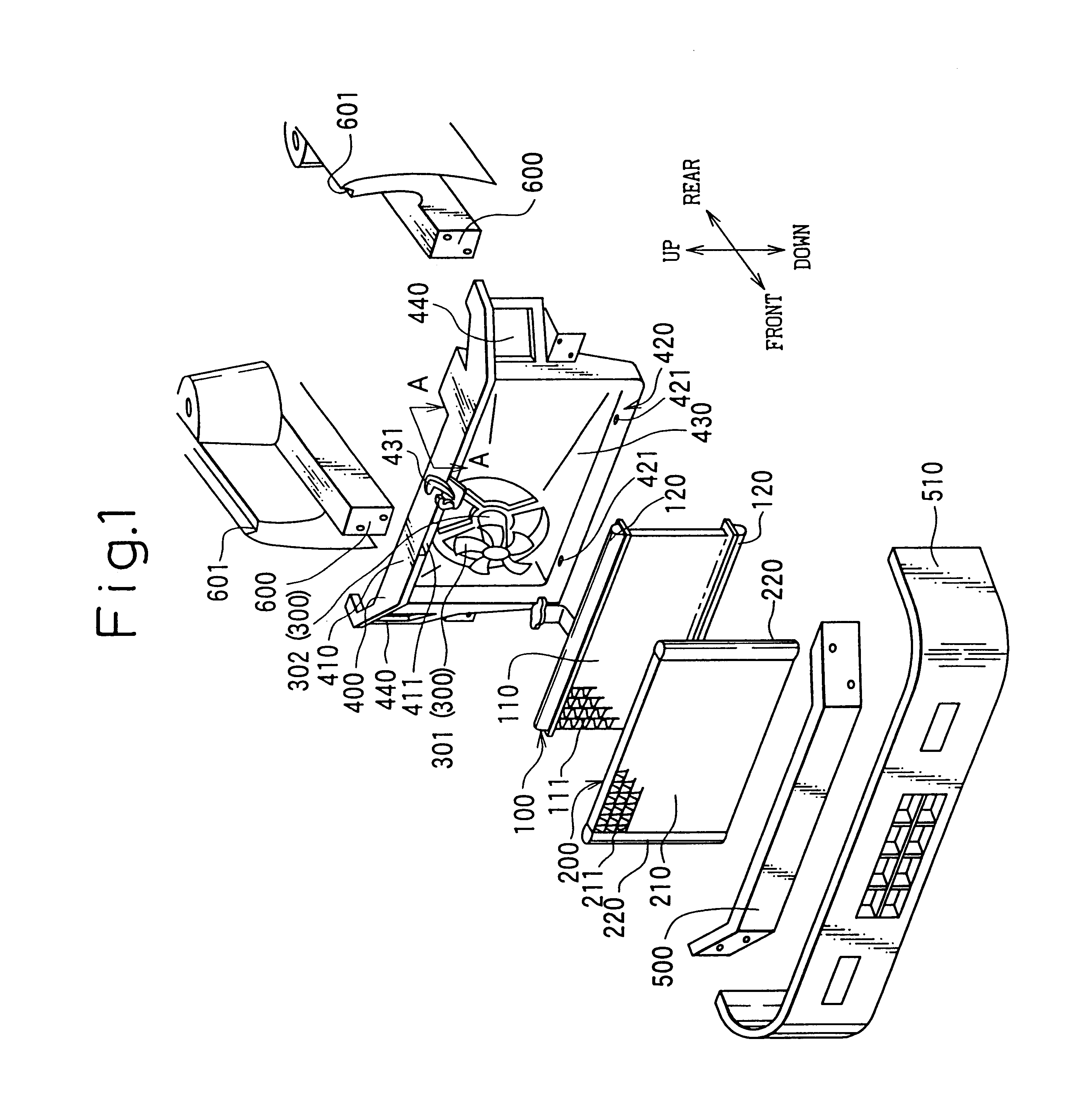
FIG. 1 is an exploded perspective view of a vehicle front end section in which an intake duct structure of the embodiment is utilized. Reference numeral 100 is a radiator, reference numeral 200 is a condenser, and reference numeral 300 is a fan device composed of a fan 301 and an electric motor 302.

In this connection, the radiator 100 is a well known multi-flow type heat exchanger including: a radiator core 110 composed of a plurality of radiator tubes 111 in which coolant flows; and radiator tanks 120 arranged on both end sides of the radiator tubes 111 in the longitudinal direction, the radiator tanks 120 communicating with the radiator tubes 111.

The condenser 200 is a well known multi-flow type heat exchanger, which is composed in the same manner as that of the radiator 200, including: a condenser core 210 composed of a plurality of condenser tubes 211 in which refrigerant flows; and condenser tanks 220 arranged on both end sides of the condenser tubes 211 in the longitudinal dir...


PUM


Abstract

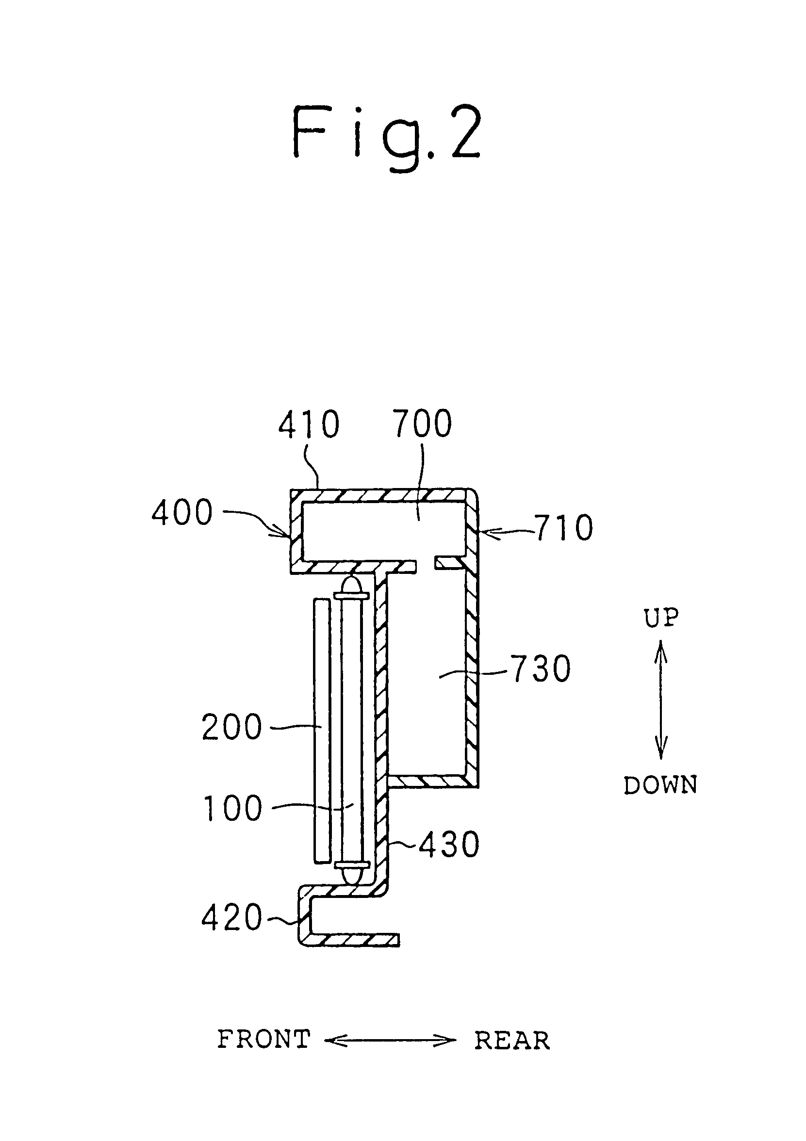
An intake duct (intake air path) utilizes an upper beam member of a front end panel, the cross section of which is substantially a C-shape. When the front end panel is assembled into a vehicle with the duct member being attached to the front end panel, assembling of the intake duct is completed. In another embodiment, a space (intake duct) is formed in a first pillar section of the front end panel with an intake port and a discharge port, which communicate the inside of the space with the outside of the space; the parts are arranged such that they are shifted from each other when they are viewed from the front side of the vehicle. Thus, a current of air flowing into the space flows in a crank-shape and passes outside of the space. Accordingly, foreign objects such as rain water and snow, which have entered the space together with air, will not flow together with the current of air flowing in the space. Therefore, the foreign objects such as rain water and snow remain in the space.

Description

This application is based upon and claims the priority of Japanese Patent Application No. 11-298495, filed Oct. 20, 1999 and No. 11-321630, filed Nov. 11, 1999, the contents being incorporated therein by reference, and is a continuation of PCT / JP00 / 07354, filed Oct. 20, 2000.1. Technical FieldThe present invention relates to a structure of an intake duct for guiding air into a vehicle engine. More particularly, the present invention relates to a front end panel having an intake duct structure which is incorporated into a front end section of a vehicle and into which vehicle front end parts including at least a radiator are incorporated.2. Background ArtIn general, an intake duct is composed in such a manner that a plurality of pipe-shaped ducts made of resin are connected with each other.However, the above means has the following disadvantages. In order to assemble the intake duct in the case of assembling a vehicle, it is necessary to incorporate a plurality of ducts into the vehic...

Claims


Application Information

Patent Timeline
Patent Type & Authority Patents(United States)
IPC IPC(8): B62D25/08
CPCB62D25/084B62D25/08
Inventor OZAWA, IKUOSASANO, NORIHISASUGIYAMA, TOSHIKI
Owner DENSO CORP
Learn More