Magnetising arrangements for torque/force sensor

a torque/force sensor and magnetic arrangement technology, applied in the direction of work measurement, measurement devices, instruments, etc., can solve the problems of inability to provide useful flux emanating from the ring, increase costs, and difficulty in implementation

Inactive Publication Date: 2003-06-24
ABAS
View PDF6 Cites 141 Cited by
  • Summary
  • Abstract
  • Description
  • Claims
  • Application Information

AI Technical Summary

Problems solved by technology

The points of saturation for the opposite drive polarities in the coil become unbalanced due to the presence of an external field and it is this unbalance that is sensed.
The consideration underlying these proposals appears to be that if the circumferentially magnetised ring were to be mounted directly to a mass of high permeability material, the flux that emanates from the ring under torque would be shunted through the shaft and no useful flux would be available emanating from the ring.
Anothr cost factor to be considered is the need to produce the ring by maching and any special measures taken on the shaft and/or ring to secure the ring against slippage under torque loads add to cost.
The practical implementation of this proposal requires additional components, i

Method used


Image

  • Magnetising arrangements for torque/force sensor
  • Magnetising arrangements for torque/force sensor
  • Magnetising arrangements for torque/force sensor

Examples


Embodiment Construction

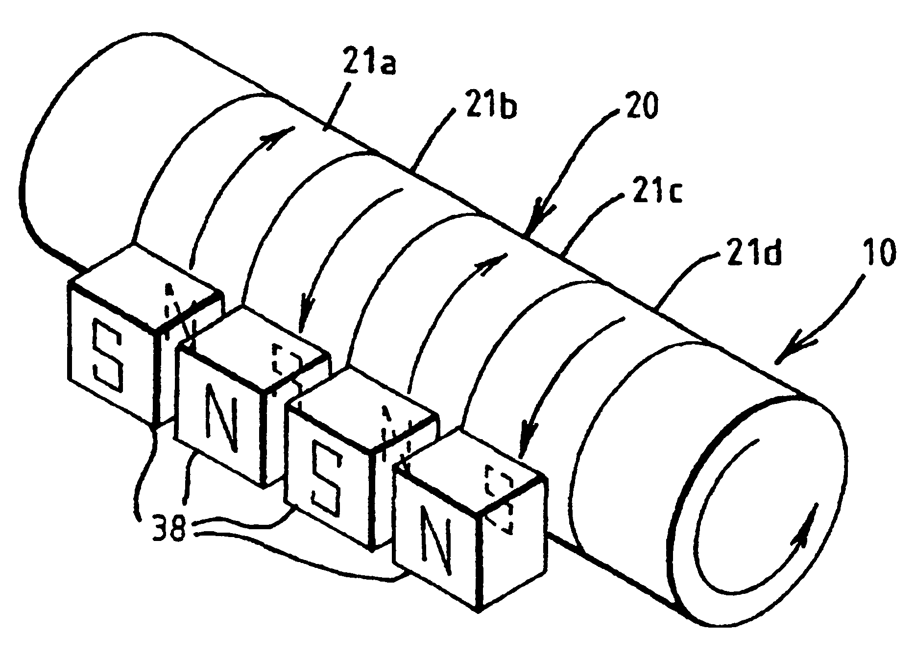
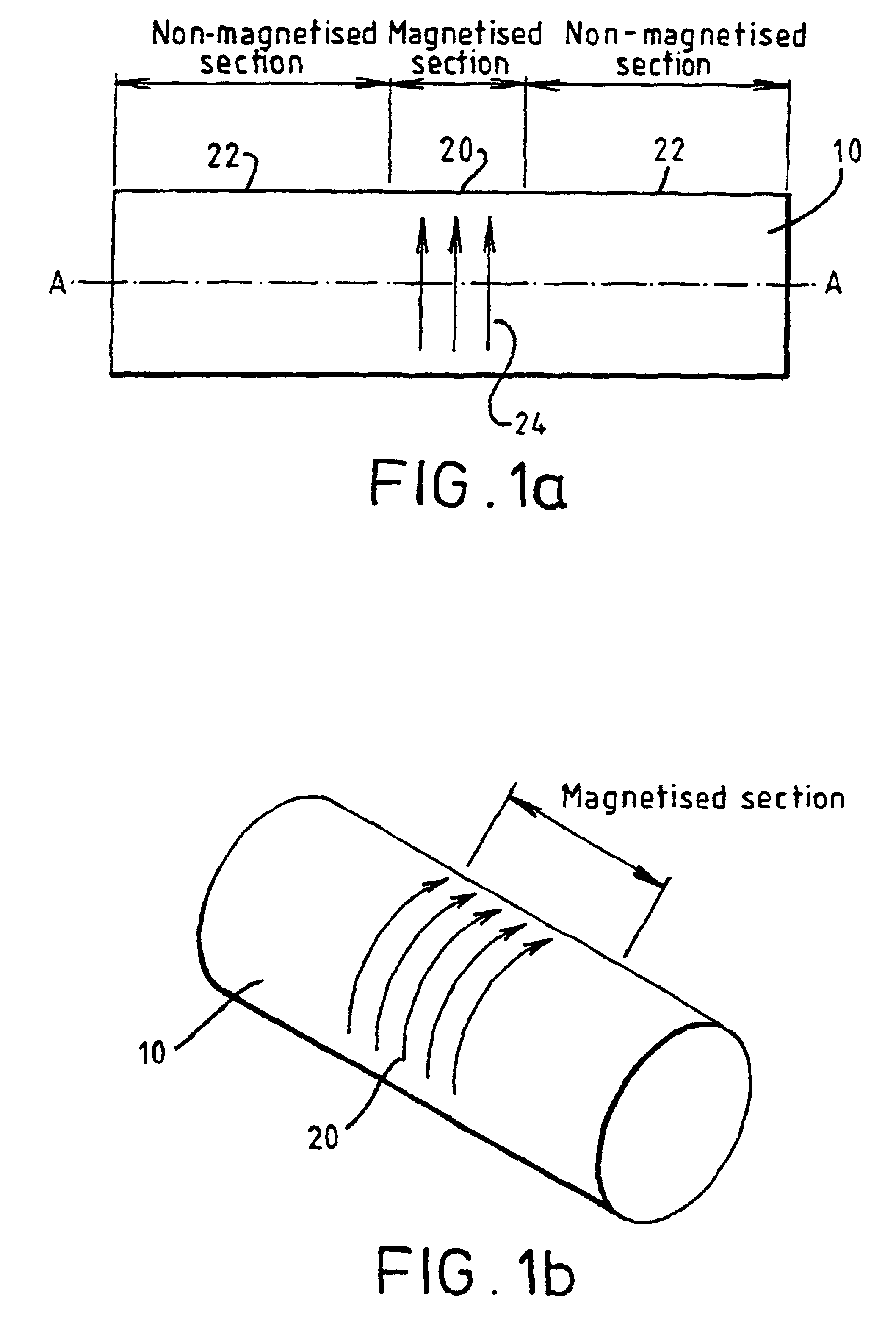
FIGS. 1a and 1b illustrate a shaft 10 of solid circular cylindrical cross-section rotatable about its longitudinal axis A--A. The shaft is of a magnetisable material. The shaft is assumed to be stationary and to have no torque applied to it about the axis of rotation. The shaft has an axially inner magnetised portion 20 bounded by outer non-magnetised portions 22. Thus as shown in the figures, the shaft 10 is a single homogeneous entity with the magnetised portion integral with or unitary with the remainder of the shaft. The magnetic field 24 extends circumferentially around the inner portion 20 and the flux is confined to the shaft. That is no flux lines emanate externally of the shaft in the absence of stress in the shaft. Within the solid shaft, the circumferential field can be visualised as penetrating inwardly like a series of concentric rings, the field getting weaker toward the centre of the shaft and vanishing at the axis. Thus the presence of a bore running through the axia...


PUM


Abstract

A magnetoclastic transducer for sensing a torque in a shaft (150) is formed by circumferentially magnetising a magnetisable, integral portion (156) of the shaft. To assist in the emanation of a flux-dependent torque, the transducer element portion (156) of the shaft may have further circumferentially magnetised portions (154, 158) to each side. These further portions (154, 158) are of opposite polarity magnetisation to that of the transducer element (156). The external magnetic flux emanated by the transducer (156) is a function of torque and is detectable by a magnetic field sensor (160). An alternative means for the same purpose is to provide the transducer element at a portion (172) of the shaft (170) having an integral annular section of raised profile projecting beyond adjoining portions of the shaft. The shaft may be provided with a series of circumferentially magnetised portions of alternating polarity. A number of ways of achieving circumferential magnetisation are described, together with other directions such as axial. A shaft having the whole or an integral portion of it magnetised can also be used to provide a force transducer sensitive to bending moment induced in the shaft by a force to be measured.

Description

This invention relates to a sensor arrangement for sensing a torque or flexural force in a shaft and to a method and apparatus for inducing a magnetic field in a shaft for sensing by a sensor arrangement. The invention also relates to shafts incorporating transducer elements and to a method of producing a magnetically calibrated shaft for use in a torque sensor.BACKGROUND TO THE INVENTIONMagnetic torque sensors are known in the art. They are based on a phenomenon commonly referred to as magnetoelasticity. Known sensors use a magnetized ring secured to a shaft so that torque in the shaft is transmitted to the ring which acts as a transducer element. The sensor also includes one or more magnetic field sensitive elements external to the ring to sense a disturbance of the magnetic field due to the torque resulting from rotation or a torque applied to a non-rotatable shaft. The rotation of any shaft from one end to drive a load at the other end generates torque in the shaft due to differ...

Claims


Application Information

Patent Timeline
IPC IPC(8): G01L3/10
CPCG01L3/102G01L3/104G01L3/103
Inventor MAY, LUTZ AXELBRODEY, NEILLOWSLEY, JOHN
Owner ABAS
Why Eureka
Try Eureka