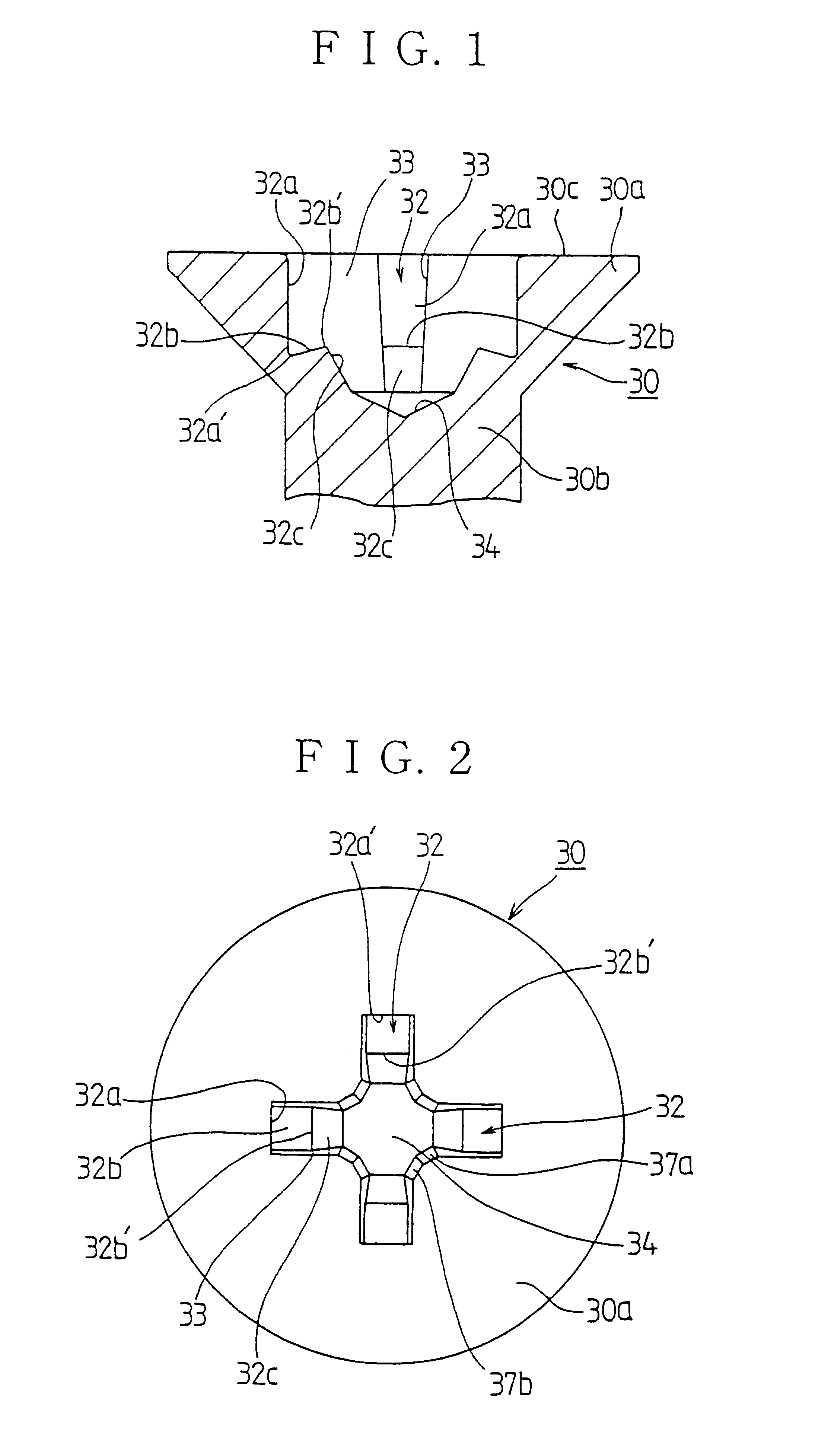
The plus-and-minus screw of the second example of the present invention is a plus-and-minus screw in which a bit fitting groove comprising of a cross groove is formed in the
screw head, one of the crossing linear grooves of the bit fitting groove is formed so that a blade of the Phillips.RTM. screwdriver bit can fit in and engage the groove, and the other linear groove is formed so that a flat-blade screwdriver bit can fit in and engage the groove. The plus-and-minus screw has the vertical end wall portion having a predetermined depth at the end edge portion of the one linear groove that the blade of a Phillips.RTM. screwdriver bit fits in and engage. Thus, the tapered contact area of the one linear groove is made partial and small upon the engagement of the tip of the driver bit with the bit fitting groove. Further, the groove bottom portion of the bit fitting groove is formed so that the area of the side wall portion that the tip of the driver bit abuts is enlarged. Thus, the com-out phenomenon of the driver bit is securely prevented.
In addition, in the screw of the first example and the plus-and-minus screw of the second example, the bit fitting groove that the blade of the drive bit fits in and engage is formed as a groove whose width is enlarged little by little from the center portion of the screw head toward the outer portion in the radial direction, so that the opening angle of the opposing side wall portion of the neighboring grooves is a little narrower than 90 degrees. Thus, balanced
torque transmission is achieved for the screw fastening operation. In addition, in the combination with a driver bit, the com-out phenomenon from the bit fitting groove of the screw can be prevented effectively.
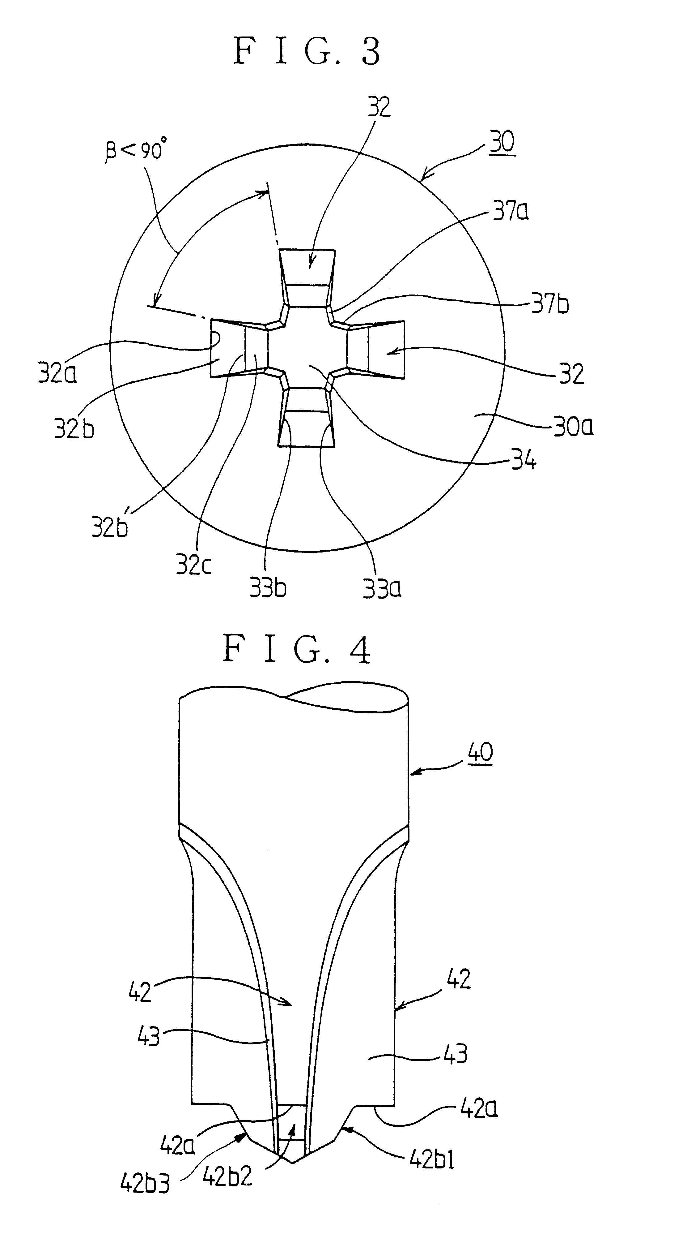
The driver bit adapted to the screw of the first example has a flat blade with a horizontal surface portion at the tip that engages the non-planar bottom portions formed at the end edge portion of the bit fitting groove of the screw, and a protrusion formed on the tip of the blade to be adapted to the shape of the groove portion extending from the non-planar bottom portions. Thus, the most suitable driver bit for the screw can be obtained.
Furthermore, the driver bit adapted to the plus-and-minus screw of the second example has flat blades having the substantially horizontal surface portions at the tip engaging the groove bottom portions formed at the end edge portion of the one linear groove of the screw, and protrusions adapted to the shape of the groove portions extending from the groove bottom portions at the end edge portion of the blade. Thus, the most suitable driver bit for the plus-and-minus screw can be obtained.
In addition, in the present invention, the screws can be
mass-produced easily and in low cost by using the header punch having the protrusions or the protruding lines that are adapted to the shape of the bit fitting groove of the screw and the plus-and-minus screw.
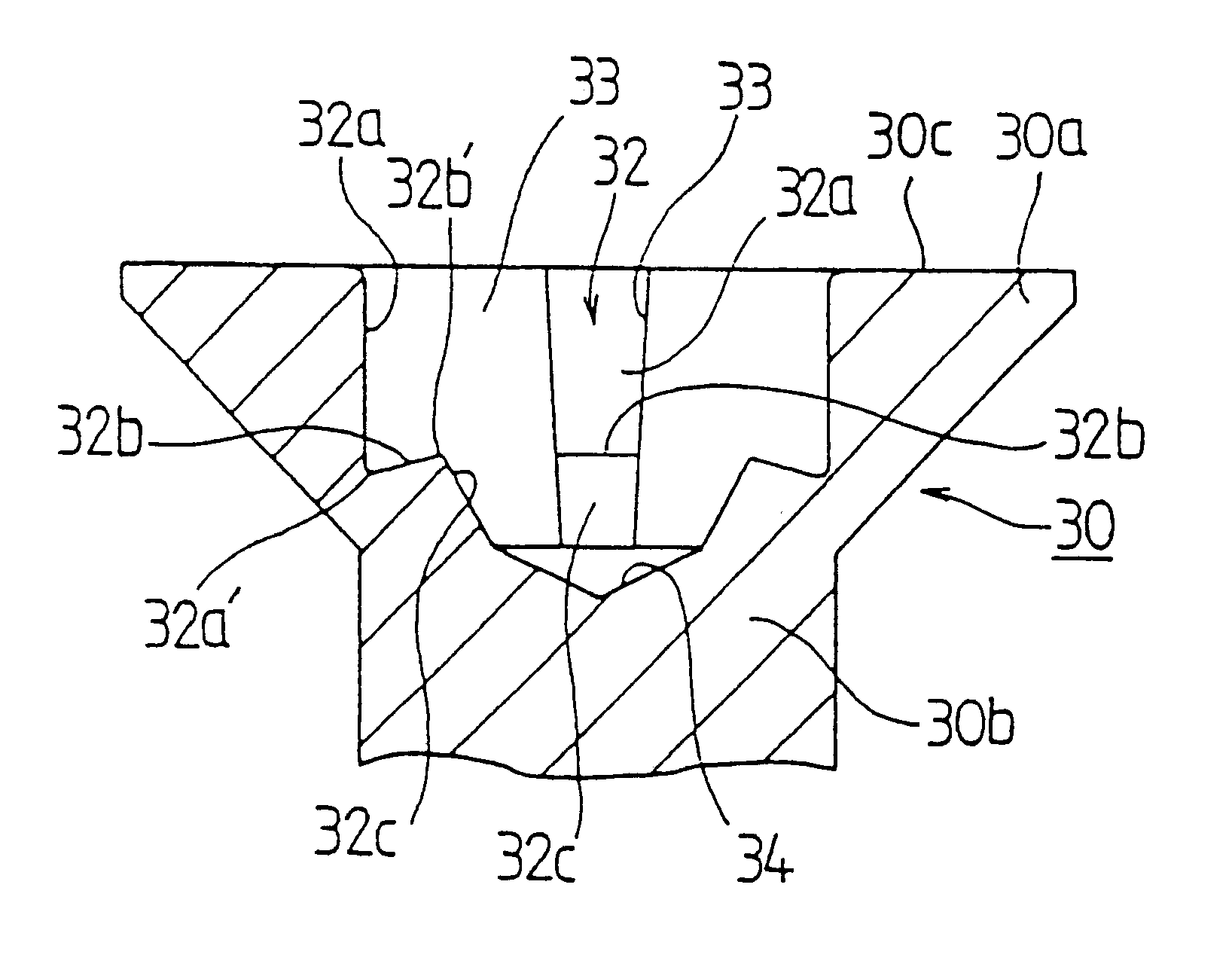
Especially, in the forming process of the bit fitting groove of the screw head of the screw and the plus-and-minus screw of the present invention, the non-planar bottom portions raised from the lower edge portion of the vertical end edge portion toward the center of the screw head by using the protrusions or the protruding lines of the header punch. In the
mass-production of the screws, even if the protrusions or the protruding lines are worn a little, the forming of the raised non-planar bottom portions is not influenced at all. Thus, the screws and plus-and-minus screws of the present invention can be
mass-produced in a low cost.
In addition, in the forming process of the bit fitting groove of the screw head in the present invention, the raised portion from the end edge portion of the vertical end wall portion toward the center portion of the screw head can keep the thickness of the screw neck properly, so that the screw having sufficient strength for fastening and loosening can be produced.
In addition, in the screw of the first example and the plus-and-minus screw of the second example, the bit fitting groove that the blade of the drive bit fits in and engage is formed as a groove whose width is enlarged little by little from the center portion of the screw head toward the outer portion in the radial direction, so that the opening angle of the opposing side wall portion of the neighboring grooves is a little narrower than 90 degrees. Thus, balanced
torque transmission is achieved for the screw fastening operation. In addition, in the combination with a driver bit, the com-out phenomenon from the bit fitting groove of the screw can be prevented effectively.
Namely, by using the combination of the screw or the plus-and-minus screw and the driver bit of the present invention, normally proper torque is applied to a hard or
soft object that the screw is fastened for secure screw-fastening operation. In addition, the breakage of the screw is reduced substantially, so that the safety of the screw-fastening operation and the working efficiency can be improved easily and economically.
In addition, the driver bit for the plus-and-minus screw of, the third example of the present invention is a driver bit for the plus-and-minus screw adapter to plus-and-minus screws having the bit fitting groove formed by a pair of linear grooves consisting of the inclined groove portion and the horizontal groove portion crossing each other at the center portion of the screw head. The drive bit has, the flat blade forming the inclined end edge portion fitting in along the inclined groove portions of the plus-and-minus screw, and the flat blade forming the horizontal end edge portion crossing the flat blade and fitting in along the horizontal groove portions, and extending substantially perpendicular to abut the groove bottom portion of the horizontal groove portion. The tip center portion of each blade is provided with a protrusion fitting in the conical-shaped bottom portion. Thus, in the same way as the other examples, upon the engagement with the screw, the engaging contact area of the side wall portion of the tip portion with the side wall portion of the bit fitting groove is enlarged. Therefore, the come-out phenomenon of the driver bit is prevented so that a proper screw-fastening operation and the screw-loosening operation can be achieved.

