Multilayer piezoelectric filter with an air vent between two resonator chambers

a piezoelectric filter and air vent technology, applied in piezoelectric/electrostrictive/magnetostrictive devices, piezoelectric/electrostriction/magnetostriction machines, electrical equipment, etc., can solve problems such as deformation of boards, and achieve strong and durable, prevent deformation, and stable characteristics

Inactive Publication Date: 2003-07-08
NGK SPARK PLUG CO LTD
View PDF10 Cites 0 Cited by
  • Summary
  • Abstract
  • Description
  • Claims
  • Application Information

AI Technical Summary

Benefits of technology

It is accordingly an object of the present invention to provide a multilayer type piezoelectric filter which is assuredly prevented from deformation even when it is heated to a high temperature and which is strong and durable so as to maintain stable characteristics for a long period of usage.

Problems solved by technology

By this, there is caused a problem that the top printed circuit board and the bottom printed circuit board are curved or rounded outside and therefore the outer casing constituted by those printed circuit boards is deformed or transformed.

Method used


Image

  • Multilayer piezoelectric filter with an air vent between two resonator chambers
  • Multilayer piezoelectric filter with an air vent between two resonator chambers
  • Multilayer piezoelectric filter with an air vent between two resonator chambers

Examples


Embodiment Construction

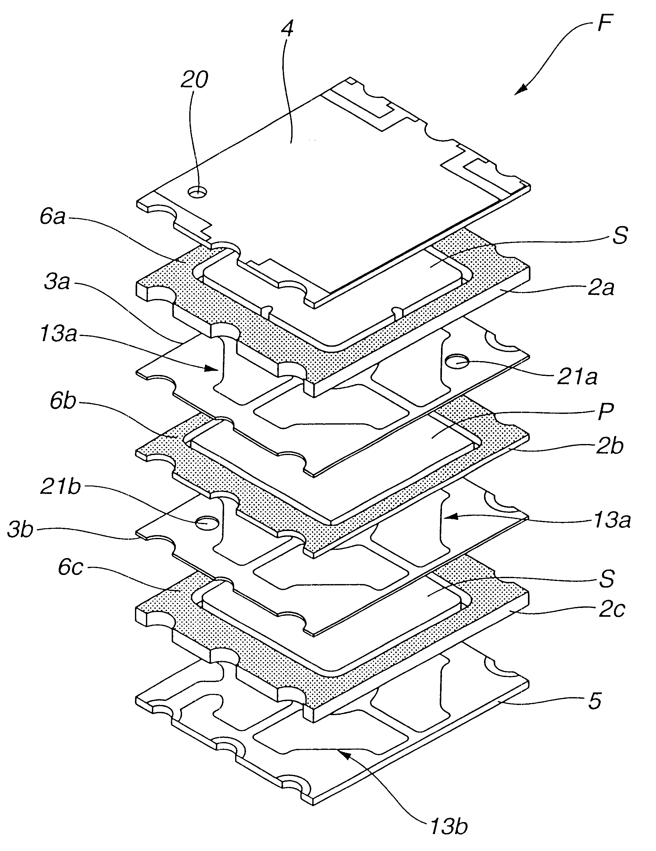
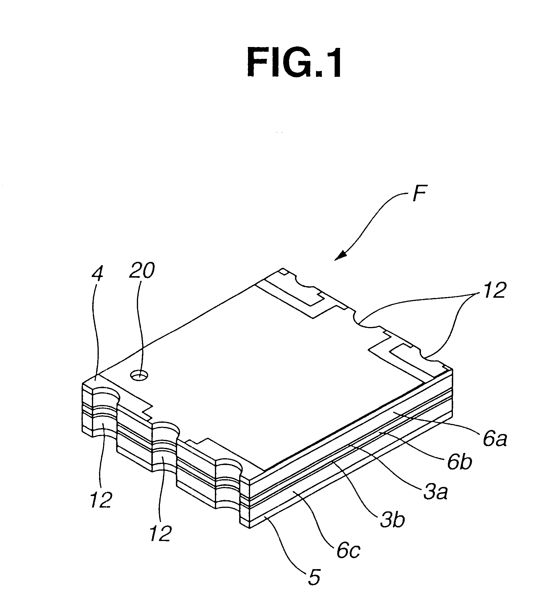
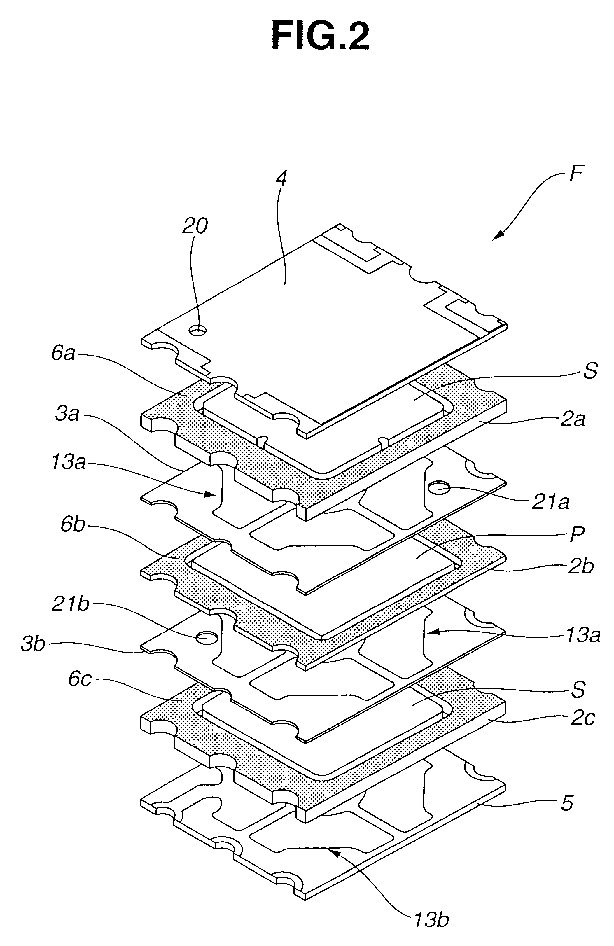
Referring first to FIGS. 1 and 2, a multilayer type piezoelectric filter according to an embodiment of the present invention is generally indicated by F and of the type having an S-P-S (series-parallel-series) structure. The piezoelectric filter F includes a series resonator S, a parallel resonator P and a series resonator S which are surrounded by respective frame-like spacers 2a, 2b and 2c and laminated one upon another with intermediate printed circuit boards 3a and 3b being interposed therebetween. A top printed circuit board 4 and a bottom printed circuit board 5 are disposed on the top of and under the bottom of the thus laminated resonators S, P and S. The frame-like spacers 2a, 2b and 2c and the printed circuit boards 4 and 5 are bonded together by means of adhesive sheets (not shown) and therefore hermetically sealed at the joining portions thereof. Each adhesive sheet is made of thermosetting resin and has a rectangular frame-like shape. The adhesive sheets are interposed ...


PUM


Abstract

A multilayer type piezoelectric filter is provided which includes at least two chambers for receiving therewithin resonators, respectively. The chambers are partly defined by a top printed circuit board and an intermediate printed circuit board. The top printed circuit board and the intermediate printed circuit board are formed with communication holes for communicating the chambers with the outside.

Description

BACKGROUND OF THE INVENTIONThe present invention relates to a multilayer type piezoelectric filter which is suited for a wave filter circuit in a mobile radio communication device such as a portable radio communication device and an automotive telephone.This kind of piezoelectric filter consists of a plurality of unit filter circuits, each including a series resonator and a parallel resonator which are connected to constitute an L-connection. The unit filter circuits are laminated one upon the other and disposed between an input terminal and an output terminal or a grounding terminal. The resonance frequency of the series resonators and the antiresonance frequency of the parallel resonators are adapted to correspond with each other, and the difference between the antiresonance frequency of the series resonators and the resonance frequency of the parallel resonators is held constant.In the conventional structure of the piezoelectric filter, resonators and terminal boards are generall...

Claims


Application Information

Patent Timeline
Patent Type & Authority Patents(United States)
IPC IPC(8): H03H9/00H03H9/58H03H9/10H03H9/17
CPCH03H9/1035H03H9/58
Inventor IWATA, TATSUOHAYASHI, KAZUHIROWATANABE, MASAYUKI
Owner NGK SPARK PLUG CO LTD
Why Eureka
Try Eureka