
Multiple segment catheter and method of fabrication

a multi-segment catheter and fabrication method technology, applied in the field of multi-segment catheters and methods, can solve the problems of complicated and expensive fabrication of these catheters

Inactive Publication Date: 2003-07-15
MEDTRONIC INC
View PDF72 Cites 176 Cited by
  • Summary
  • Abstract
  • Description
  • Claims
  • Application Information

AI Technical Summary

Benefits of technology

and the objects, advantages and features thereof have been presented here simply to point out some of the ways that the invention overcomes difficulties presented in the prior art and to distinguish the invention from the prior art and is not intended to operate in any manner as a limitation on the interpretation of claims that are presented initially in the patent application and that are ultimately granted.

Problems solved by technology

Difficulties in endovascular positioning, however, make it desirable to impart high tensile and column strength over at least the proximal portion of the catheter.
The fabrication of these catheters can be complicated and expensive.

Method used


Image

  • Multiple segment catheter and method of fabrication
  • Multiple segment catheter and method of fabrication
  • Multiple segment catheter and method of fabrication

Examples


Embodiment Construction

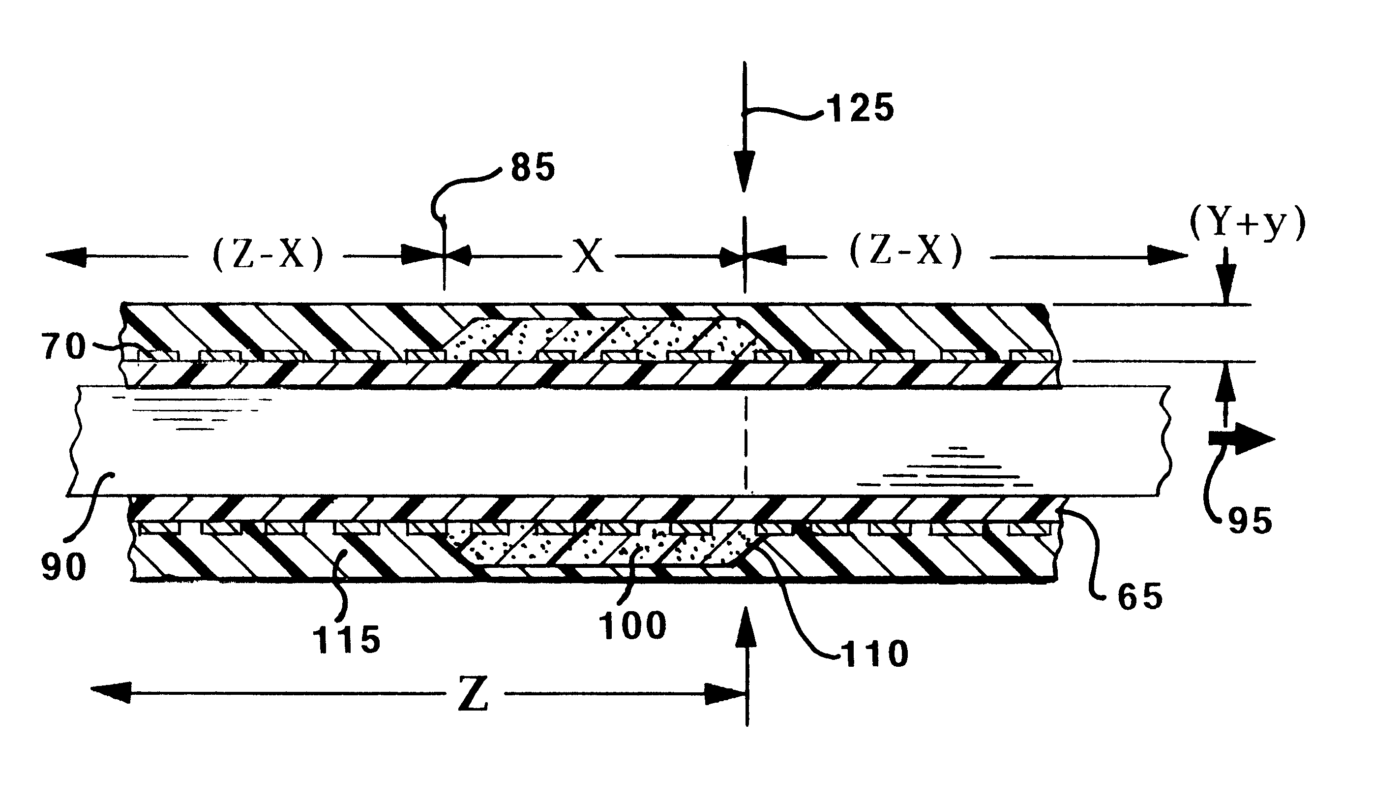
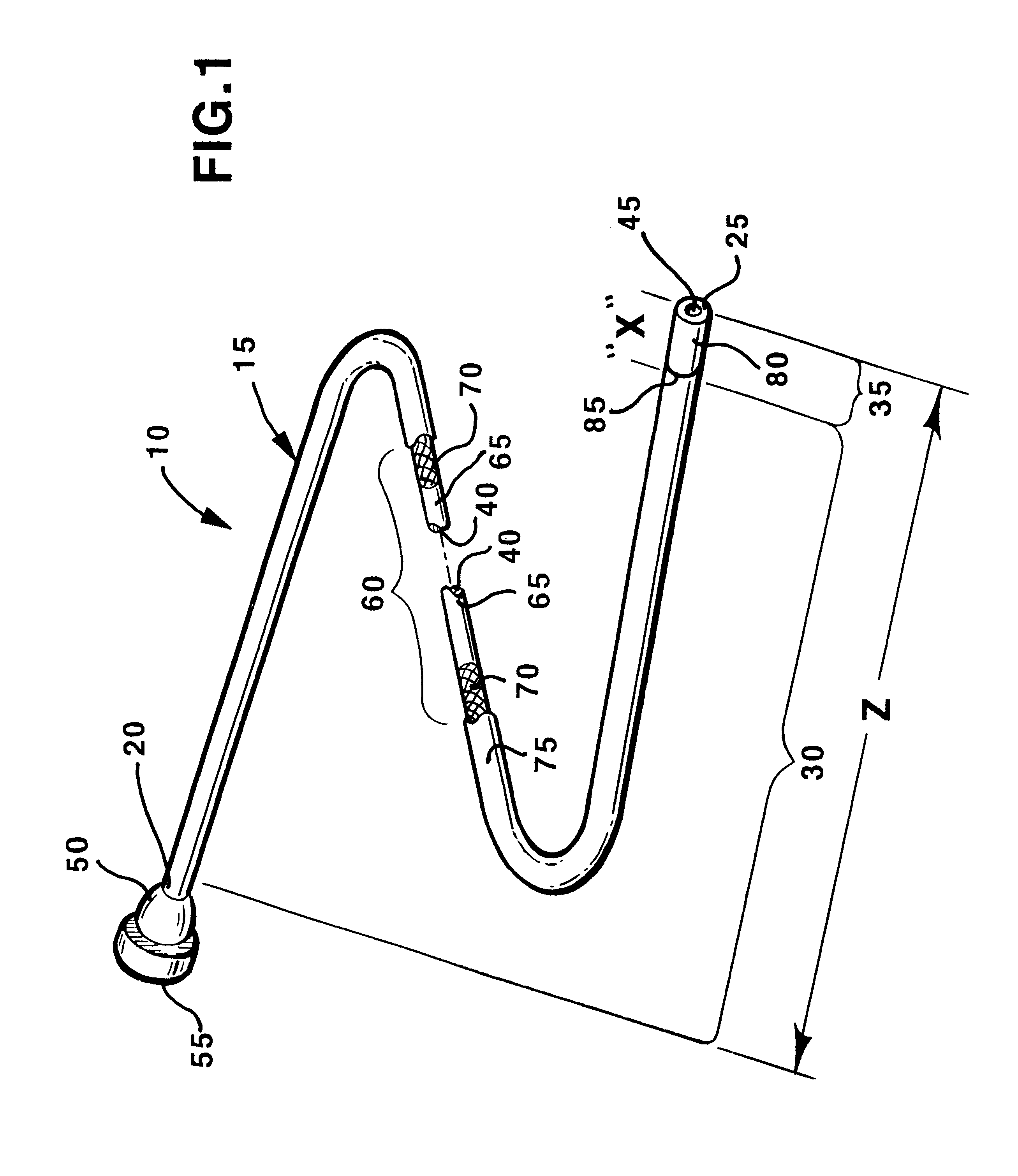
FIG. 1 illustrates a two section embodiment of a medical catheter 10 constructed in accordance with the principles of the present invention having a catheter body 15 extending between a proximal catheter body end 20 and a distal catheter body end 25 and formed of a proximal catheter section 30 and a distal catheter section 35 that have differing flexibilities. The flexibility of the catheter body 15 is controlled by selecting the relative lengths and mechanical characteristics of each of these components. A catheter lumen 40 extends through the length "Z" of the catheter body 15 from a catheter lumen distal end opening 45 to a proximal connector 50 and then extends proximally through connector 50 to a catheter lumen proximal end opening 55. The catheter lumen 45 is provided within an inner liner of a tubular inner jacket 60 described below and allows for the passage of a diagnostic or therapeutic fluid or other device through it and / or allows for the catheter body 15 to be advanced ...


PUM

PropertyMeasurementUnit
lengthaaaaaaaaaa
lengthaaaaaaaaaa
lengthaaaaaaaaaa

Abstract

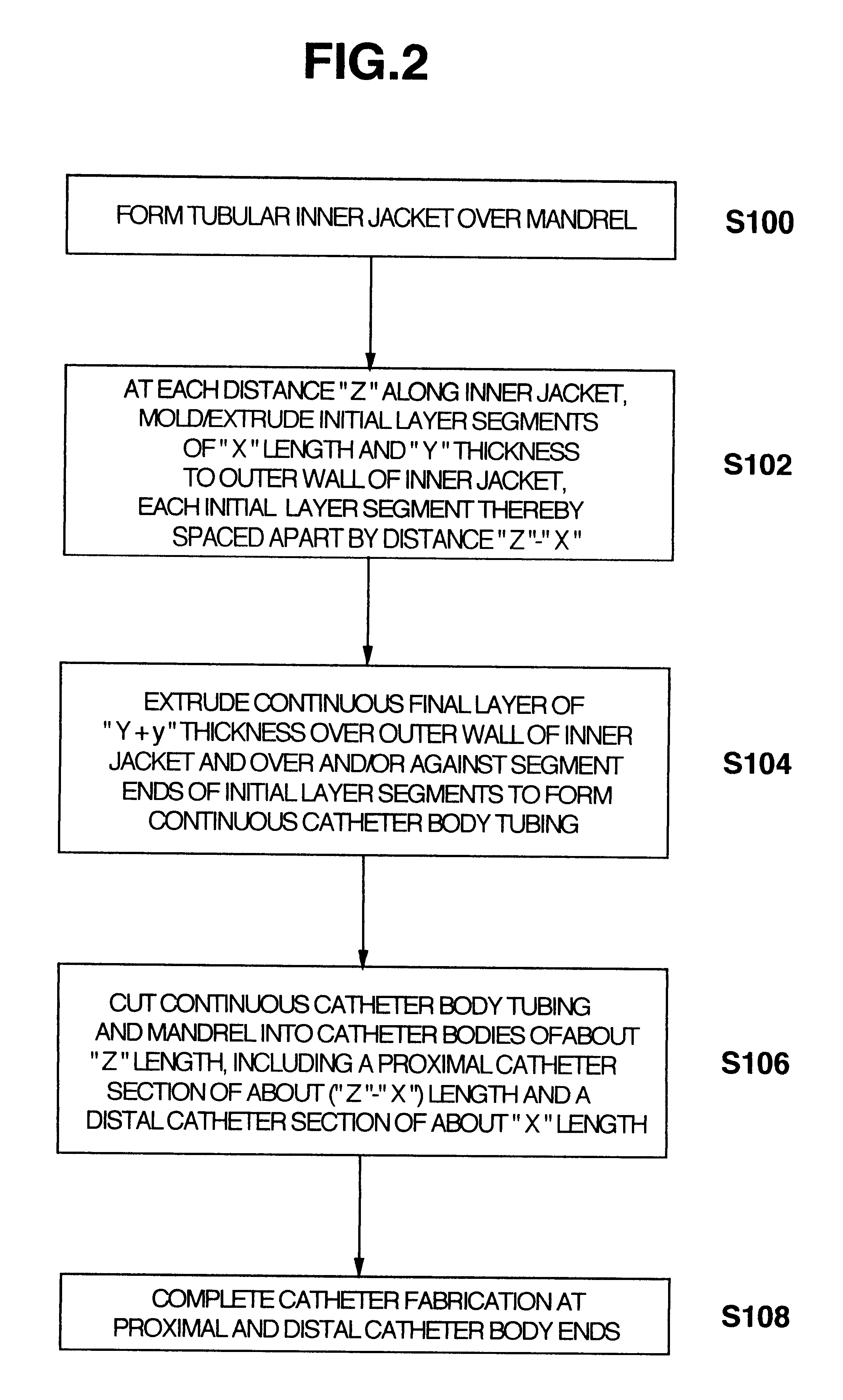
Methods of fabricating medical vascular catheters adapted to be inserted into a blood vessel from an incision through the skin of a patient for introducing other devices or fluids for diagnostic or therapeutic purposes and particularly methods for fabricating such catheters with catheter bodies having catheter sections of differing flexibility are disclosed. Such catheter bodies having a proximal catheter body end and a distal catheter body end and formed of a proximal section and at least one distal section that have differing flexibilities are formed in a process comprising the steps of: (1) forming a continuous tubular inner jacket preferably of an inner liner and a reinforcement layer; (2) forming initial layer segments having an initial layer thickness along the length of the inner jacket from a material of first durometer hardness, whereby each initial layer segment is separated by a separation distance: (3) forming a final layer of a material of second durometer hardness with a second layer thickness over the tubular inner jacket along the separation distances and over and / or against the proximal and distal initial layer ends of the initial layer segments to form a continuous catheter body tubing; (4) severing the continuous catheter body tubing into catheter body lengths including a proximal catheter section formed of the material of second hardness and a distal catheter section of the material of first hardness; and (5) completing the catheter fabrication at the proximal catheter body end and the distal catheter body end. Centerless grinding of the catheter body or body tubing, formation of Intermediate catheter body sections, distal soft tips, and discontinuities in the reinforcement layer formed prior to step (2) are also disclosed.

Description

The present invention relates to methods of fabricating medical vascular catheters adapted to be inserted into a blood vessel from an incision through the skin of a patient for introducing other devices or fluids for diagnostic or therapeutic purposes and particularly methods for fabricating such catheter bodies with catheter sections of differing flexibility.Catheters are tube-like medical instruments that are inserted into a body cavity, duct, tract, organ or blood vessel for a wide variety of diagnostic or therapeutic reasons, including delivery of diagnostic radiopaque materials, infusion of therapeutic drugs, performance of other interventional procedures, drainage of body cavities, organs or vessels, perfusion, and the like. Medical vascular catheters for each of these purposes can be introduced to numerous target sites within a patient's body by guiding the catheter through an incision made in the patient's skin and a blood vessel and then through the vascular system to the t...

Claims


Application Information

Patent Timeline
Patent Type & Authority Patents(United States)
IPC IPC(8): A61M25/00A61M25/16
CPCA61M25/0009A61M25/0045A61M25/0012A61M25/0015Y10T29/49982B29L2031/7542Y10T29/49798
Inventor NOONE, MICHAEL S.DUNFEE, ALBERT H.POOLE, MATTHEW S.
Owner MEDTRONIC INC
Learn More