Work light cage attachment system

a technology for attaching systems and work lights, which is applied in the direction of lighting support devices, protective devices for lighting, lighting and heating apparatus, etc. it can solve the problems of large quantities with very small profit margins, additional cost of shipping work lights to the united states for sale, and the size and shape of retail containers, so as to achieve the effect of reducing the overall size of the shipping box and being easy to attach

Inactive Publication Date: 2003-07-22
COLEMAN CABLE INC
View PDF11 Cites 1 Cited by
  • Summary
  • Abstract
  • Description
  • Claims
  • Application Information

AI Technical Summary

Benefits of technology

which will become apparent are met by an improved work light cage attachment system that enables the work light to be shipped with the cage detached so that the overall size of the shipping box may be reduced. During assembly, the cage is easily attached to the work light without a hand tool yet requires the use of a hand tool for its removal. The system includes a cage that securely attaches to the faceplate over the glass opening on the work light. The cage includes a plurality of horizontal and vertical frame members. Attached to each comer and perpendicularly aligned to the cage planar surface is a rearward extending leg. Each leg includes a perpendicularly aligned foot that, during assembly, extends outwardly into a gap opening located between the inside surface of the faceplate and the glass. Attached to each foot is a clip with a central extending stop member. Formed on the inside surface of the faceplate adjacent to the upper and lower edges of the glass opening are two raised lips. During operation, the legs may be easily forced together and inserted into the four comers of the glass opening so that the clips are inserted into the gap openings located between the faceplate and the glass. The lips prevent the removal of the stop members without a hand tool, thus meeting Underwriters Laboratories code.

Problems solved by technology

Because a large number of companies manufacture these work lights, they must be sold at competitive prices in large quantities with very small profit margins.
One drawback of doing so is the additional cost of shipping the work lights to the United States for sale.
One factor that influences the cost of shipping is the size and shape of the retail container.

Method used


Image

  • Work light cage attachment system
  • Work light cage attachment system
  • Work light cage attachment system

Examples


Embodiment Construction

)

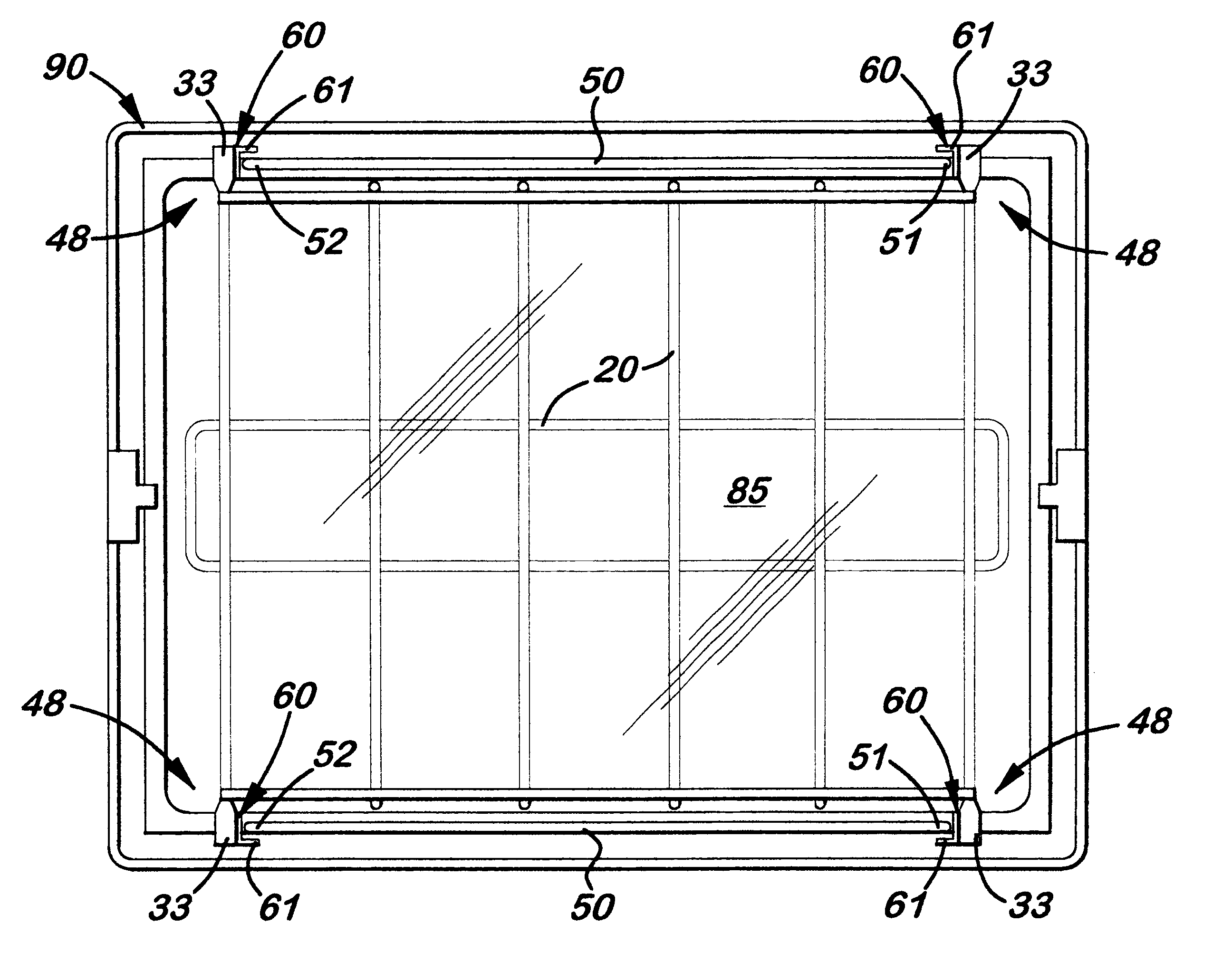
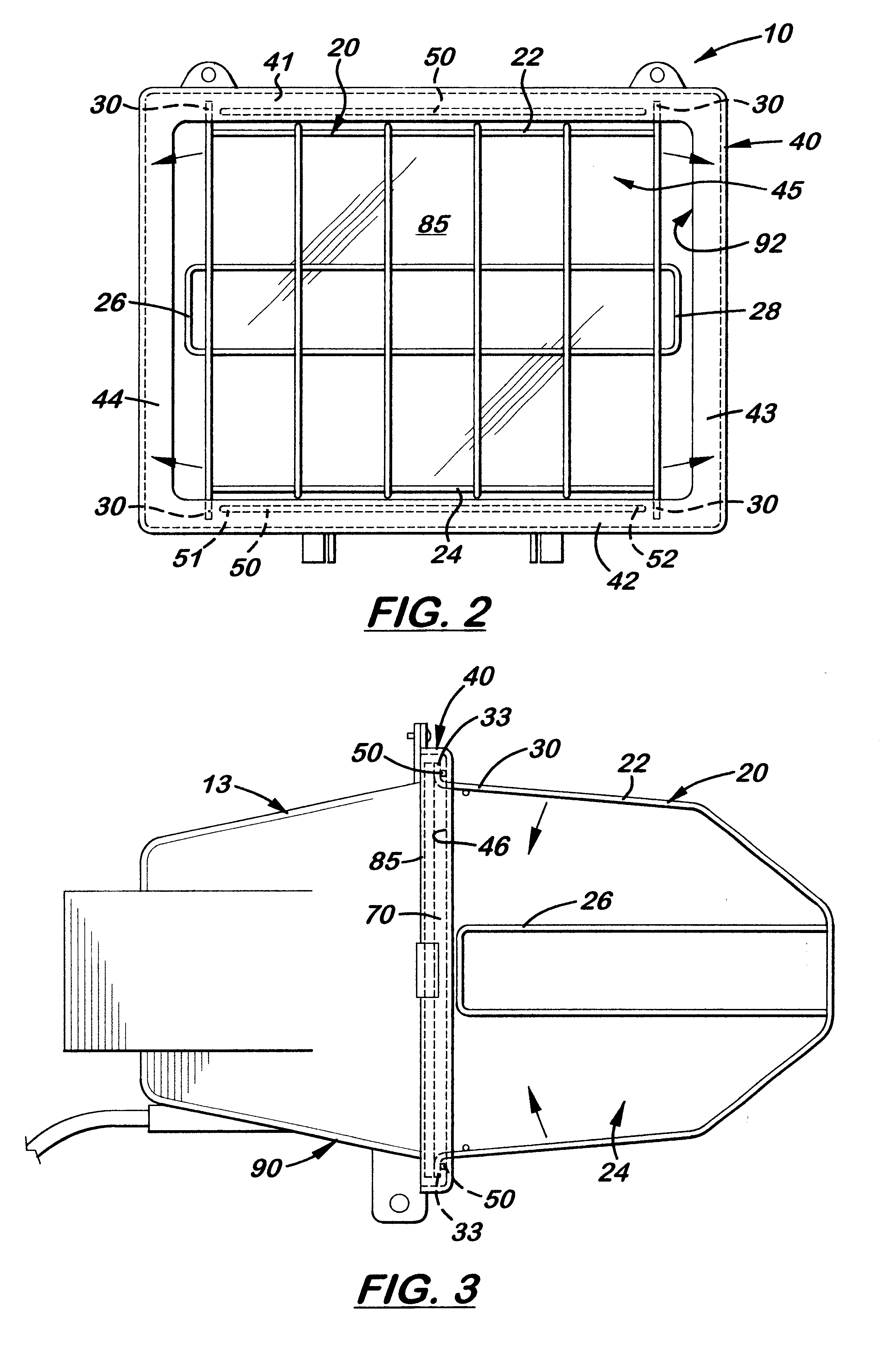
Referring to the accompanying FIGS. 2-6, there is shown and described a work light cage attachment system generally referenced as 10 which includes a cage 20 that securely attaches to an improved faceplate 40 that covers the front opening 92 on a work light 90. The cage 20 includes opposite top and bottom frame members 22, 24, respectively, and opposite side frame members 26, 28. Attached to the corners of the top and bottom frame members 22, 24 and longitudinally aligned with the side frame members 26, 28 are rearward extending legs 30.

The improved faceplate 40 is a square or rectangular structure with parallel top and bottom members 41, 42 and parallel side members 43, 44 located centrally in a glass opening 45. Attached or formed on the inside surface 46 of the faceplate 40 immediately adjacent to the top and bottom members 41, 42 of the glass opening 45 are horizontally aligned elongated lips 50. Each lip 50 is shorter than the width of the glass opening 45 thereby creating an ...


PUM


Abstract

A work light cage attachment system which includes a cage that securely attaches over the glass opening on a work light. The cage includes opposite top and bottom frame members and opposite side frame members. Attached to the comers of the top and bottom frame members are rearward extending legs. Each extending leg includes a perpendicularly aligned foot that, during assembly, is placed inside the gap between the edge of the faceplate and the glass and extends outward to prevent disengagement of the cage from the faceplate. Attached to each foot on the top and bottom frame members is a C-shaped clip which engages a raised lip formed on the inside surface of the faceplate. The lips prevent the cage from being removed from the work light without a tool, thus meeting United Laboratories code.

Description

1. Field of the InventionThis invention pertains to work lights, and more particularly, to work lights with a protective outer cage attached to the front of the light.2. Description of the Related ArtPortable work lights are manufactured and sold by many companies. Because a large number of companies manufacture these work lights, they must be sold at competitive prices in large quantities with very small profit margins.Most portable work lights 12 in the prior art (FIG. 1) include an outer housing 13 which contains the bulb 14 with a square or rectangular-shaped piece of glass 15 covering a front opening 16. The piece of glass 15 protects the bulb 14 by preventing objects, water, and dirt from entering the outer housing 13. The piece of glass 15 is held in place on the housing 13 by a removable faceplate 17. Screws or other suitable connectors (not shown) are used to attach the faceplate 17 to the outer housing 13. Clips (not shown) are used to attach the piece of glass 15 to the i...

Claims


Application Information

Patent Timeline
Patent Type & Authority Patents(United States)
IPC IPC(8): F21V15/02F21V15/00F21V17/00F21V17/16
CPCF21V15/02F21V17/007F21V17/164F21W2131/1005
Inventor TSAO, FRANK
Owner COLEMAN CABLE INC
Why Eureka
Try Eureka