Method of and cassette structure for burn-in and life testing of multiple LEDs and the like

a technology of leds and cassettes, applied in the direction of individual semiconductor device testing, optical radiation measurement, instruments, etc., can solve the problems of significant data loss, difficult to achieve a high-level of photometric or radiometric measurement accuracy, and the difference in the size of light bulbs

Inactive Publication Date: 2003-07-22
LABSPHERE
View PDF9 Cites 28 Cited by
  • Summary
  • Abstract
  • Description
  • Claims
  • Application Information

AI Technical Summary

Benefits of technology

n object of the present invention, therefore, is to provide a new and improved method of and cassette structure for hi

Problems solved by technology

With LEDs, on the other hand, it is often difficult to achieve a high-level of photometric or radiometric measurement accuracy due to uncertainties within that type of measurement equipment and test set-up.
Additionally, traditional photometrics, because of their inability to simulate the response of the human eye at the ends of the visible spectrum, can generate

Method used


Image

  • Method of and cassette structure for burn-in and life testing of multiple LEDs and the like
  • Method of and cassette structure for burn-in and life testing of multiple LEDs and the like
  • Method of and cassette structure for burn-in and life testing of multiple LEDs and the like

Examples


Embodiment Construction

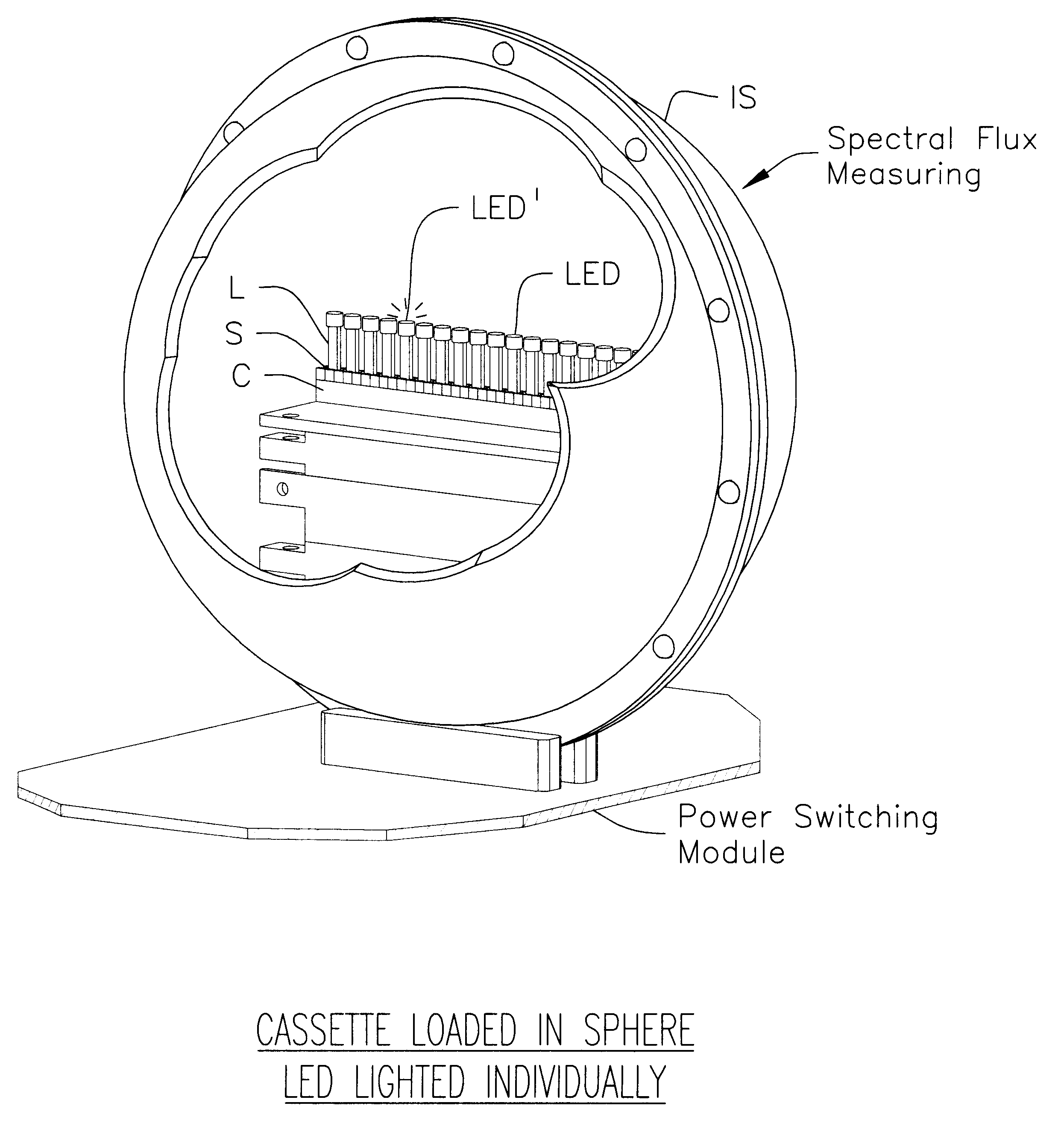
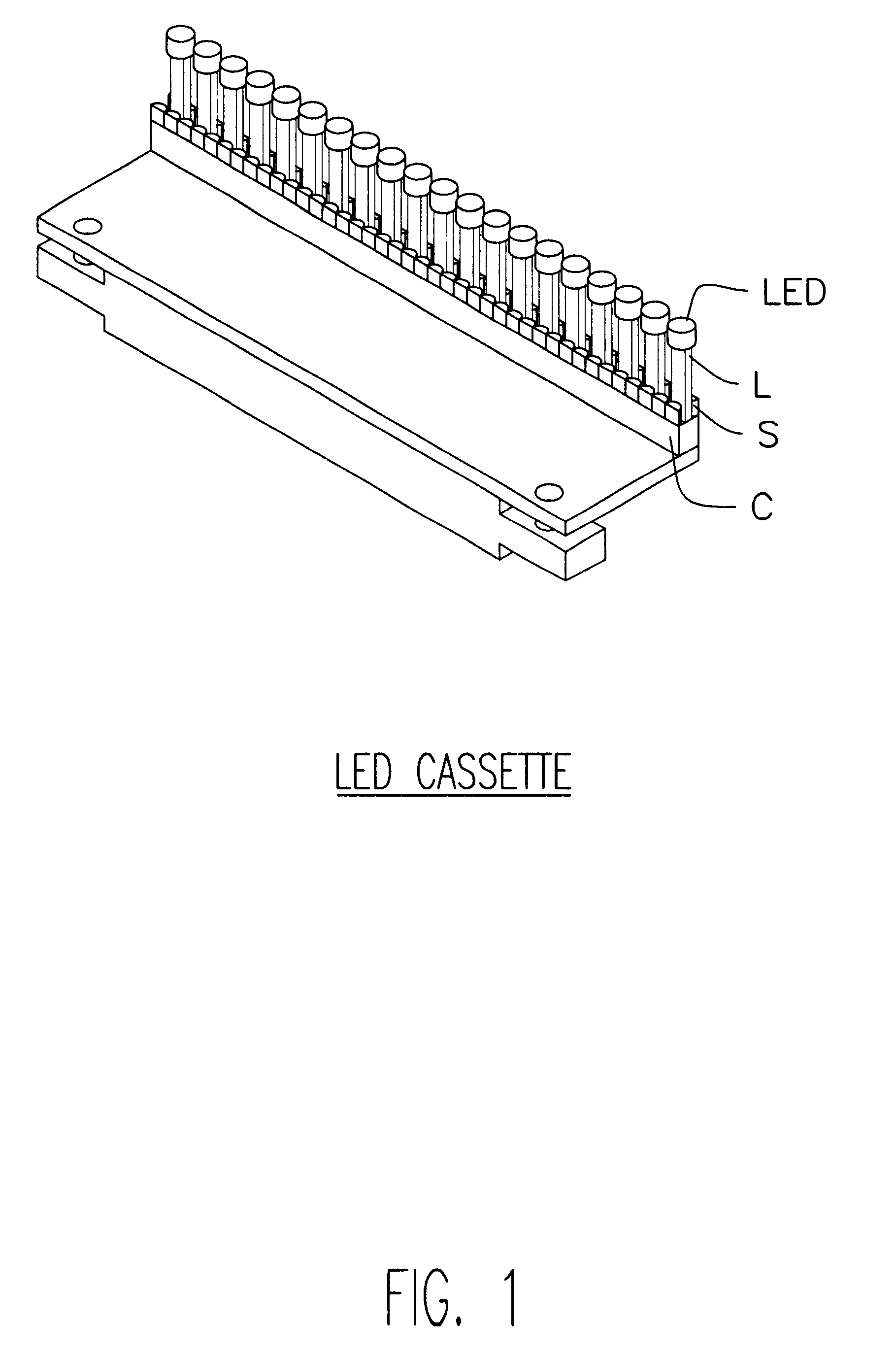
As above explained, the drawings show preferred LED cassette and measurement structures designed in accordance with the present invention to serve as a multi-purpose LED test station adapted for high volume throughput. The system applies a variety of optical and electrical test measurements to arrays of LEDs plugged into longitudinally extending cassettes, shown at C in FIGS. 1, 2 and 4, with the LED lead conductors L plugged into a row of spring contacts S, illustrated as mounted along the inner upper edge of the cassette.

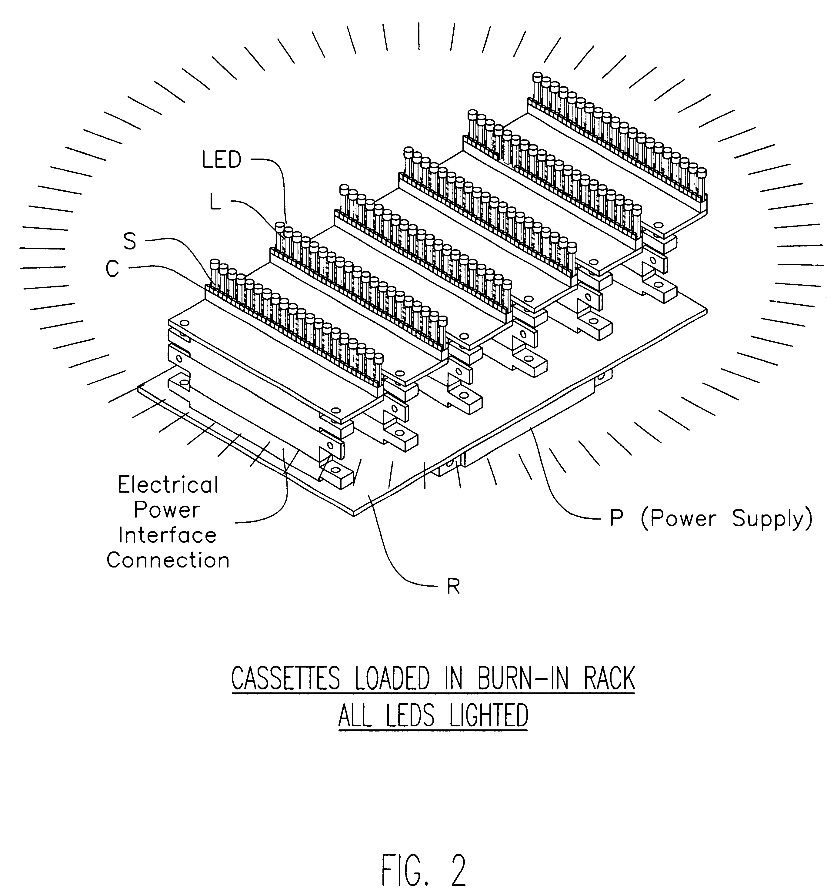
For the burn-in phase above mentioned, parallely mounted pluralities of such cassettes C are mounted, (shown in FIG. 2 as each carrying 20 LEDs), upon electrical power interface bar connections, so-labeled, and mounted as a burn-in rack R. The burn-in function is performed by providing power at P, FIG. 2, and at VCC, FIG. 3, simultaneously to all the LEDs of all the cassettes C to light them all for the desired burn-in period.

As earlier described, in the subsequen...


PUM


Abstract

A novel cassette structure technique for enabling simultaneous burn-in of pluralities of LEDs plugged into the cassettes, and then, with the cassettes mounted within a light integrating sphere system, separately measuring the spectral flux emitted by each successive individual LED plugged into the cassette to determine optical and electrical characteristics of each LED separately from the others.

Description

The present invention relates to apparatus and techniques for aiding the design, quality control and manufacturing testing of light sources, being more particularly directed to light emitting diode (LED) light sources and the use of integrating spheres for measuring their output.Manufacturers of various lamp-type light sources have long used optical integrating spheres for measuring the output characteristics of the lamps both during the design and quality control processes. In the design phase, integrating spheres are used to test new designs, and in the manufacturing phase, for SPC (statistical process control) testing and then life testing with periodic measurements of the lamp output characteristics of each lamp. Current integrating spheres are, for example, of the type described in U.S. Pat. No. 5,537,203 of Labsphere Inc., the common assignee of the present invention, marketed under the mark Spectralon.RTM., further described in an article entitled Handbook of Applied Photomet...

Claims


Application Information

Patent Timeline
IPC IPC(8): G01J1/08
CPCG01J1/08G01J2001/4252
Inventor BEAUDRY, DAVID N.DURELL, CHRISTOPHER N.KULACZ, JAMES F.
Owner LABSPHERE
Why Eureka
Try Eureka