Regulator device for controlling the power of a transmitter

a technology of a regulator device and a transmitter, which is applied in the direction of transmission, amplification control, electrical equipment, etc., can solve the problems of large spectrum occupied, information can be lost, and the transmission power needs to be only just enough, so as to achieve the effect of reacting more quickly

Inactive Publication Date: 2003-08-05
DRNC HLDG INC
View PDF7 Cites 2 Cited by
  • Summary
  • Abstract
  • Description
  • Claims
  • Application Information

AI Technical Summary

Benefits of technology

An object of the present invention is to remedy the problem as posed above at the terminal, and it seeks to reach the desired power level quickly following a stimulus of the input signal at the determined input of the power amplifier.
Thus, the device of the invention with adjustment means other than the prior art regulation loop and reacting more quickly to the signal input to the power amplifier makes it possible to reach a desired power level for transmission more quickly. The transfer function of the power amplifier is modified for this purpose.

Problems solved by technology

The transmitted power needs to be only just sufficient because of the limited amount of power available in the terminal.
Unfortunately, the way in which a power amplifier increases its output power varies from one amplifier to another depending on the particular components constituting it, on the drift to which it might have been subject, .
Thus, if power rises too slowly, then information can be lost, whereas if power rises too quickly then that will occupy a large amount of spectrum which will be detrimental to the calls of other terminals.
Consequently, from the above, it can be seen that in prior art terminals, the length of time it takes to raise the power from a power amplifier is not only undeterminable, but it can also be too long to guarantee that the required quality of service is complied with.

Method used


Image

  • Regulator device for controlling the power of a transmitter
  • Regulator device for controlling the power of a transmitter
  • Regulator device for controlling the power of a transmitter

Examples


Embodiment Construction

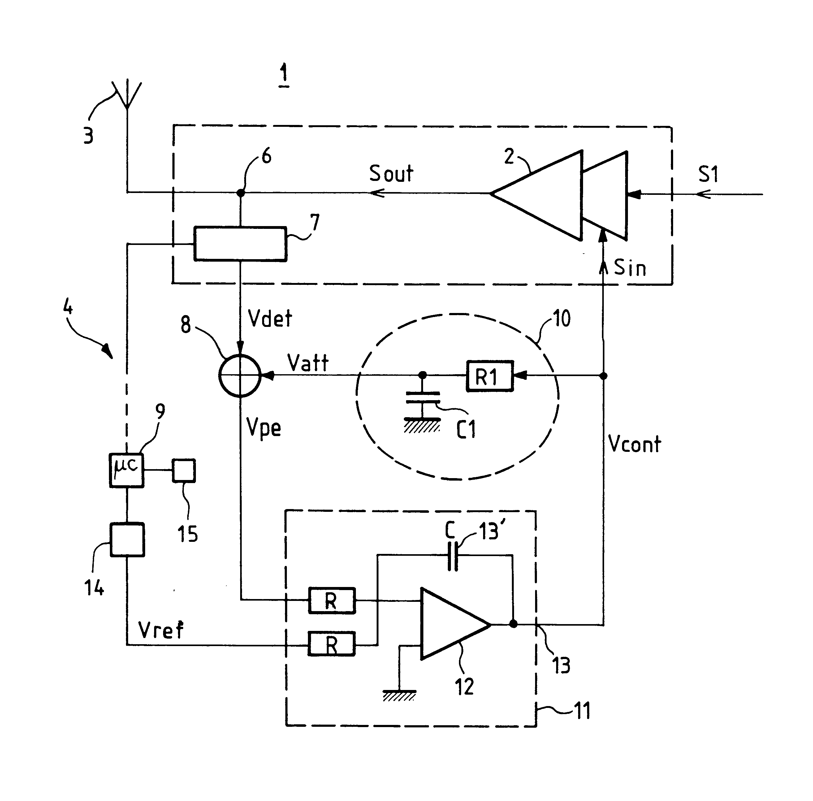
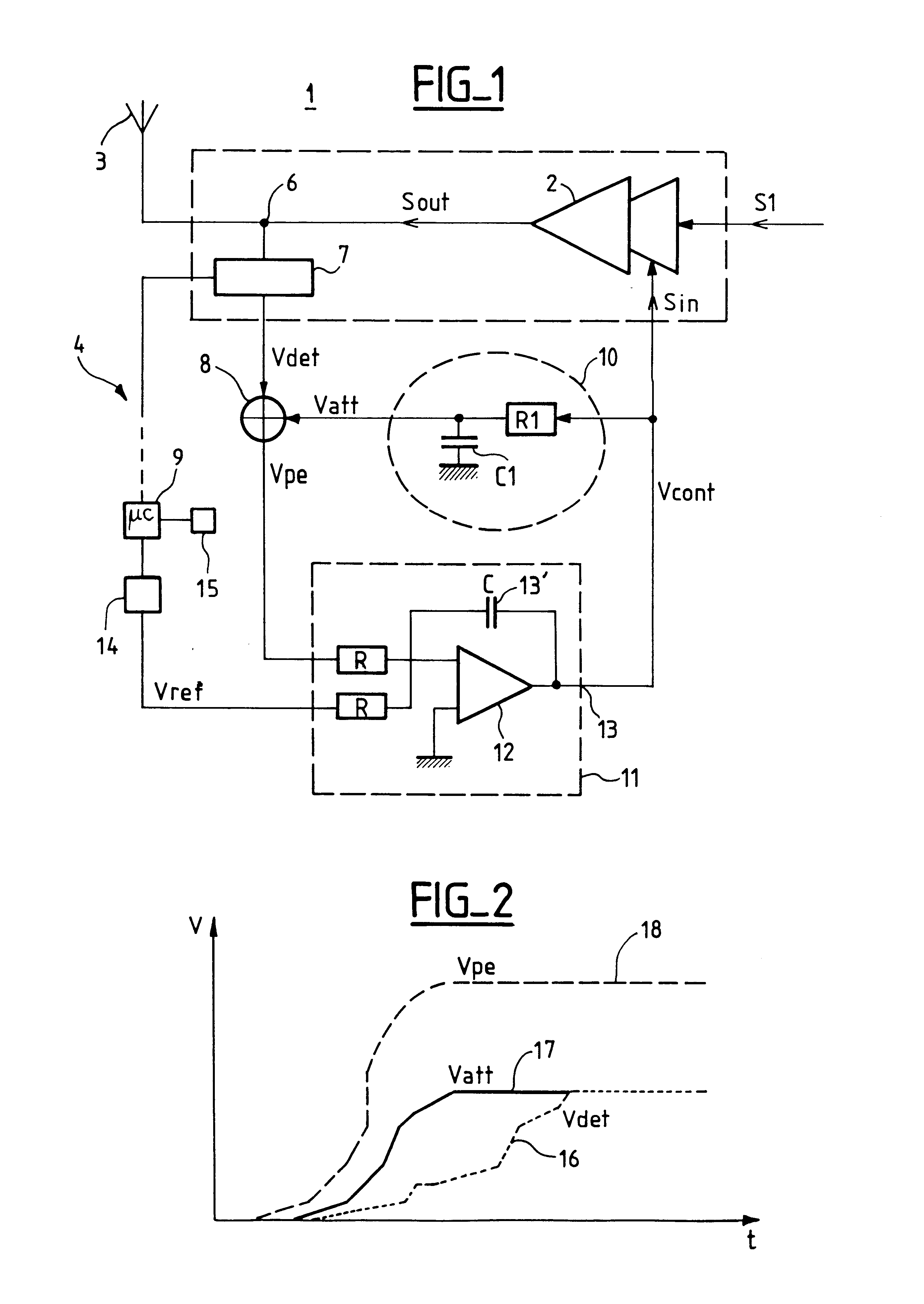
The device 1 in the embodiment of the invention shown in FIG. 1 is illustrated so as to emphasize the various functional components of the invention.

The power amplifier 2 receives an input signal Sin that is to be amplified. This signal comes from processor blocks upstream. For example, in the context of a mobile telephone, speech in the form of soundwaves is converted into an analog signal, and then into a digital signal. This is subjected to modulation and then to frequency transposition so as to put the baseband signal onto a higher frequency. As mentioned above, this signal needs to be subjected to power amplification in such a manner as to be capable of being received by the base station (not shown) that is in communication with the terminal.

The output signal Sout from the amplifier is then applied to an antenna 3 for communication with the base station.

The signal Sout is also applied to a loop 4 (on one of its branches) via an output 6 of the amplifier delivering the signal So...


PUM


Abstract

The invention relates to a device for transmitting radiofrequency signals using a power amplifier. The power amplifier is connected to a power regulation loop for regulating its gain in such a manner as to bring the output power level to a desired nominal level. The regulation loop acts on the bias voltage as a function of the output from the power amplifier. According to the invention, the device further comprises adjustment means such as an integrating RC circuit for supplying an additional voltage to the regulation loop in such a manner that the input signal to the loop is more responsive and less dependent on the active components of the power amplifier. The invention is particularly applicable in the field of mobile transmission.

Description

The present invention relates to the field of transmitting radiofrequency signals, and it relates more particularly to a device for transmitting radiofrequency signals, the device comprising power amplifier means for amplifying the power of a radiofrequency signal received at an input of said power amplifier means, and gain control means for controlling the gain of said power amplifier means to regulate said gain in such a manner that the power of the output signal from said power amplifier means tends towards a desired nominal value.In a telecommunications system connecting a mobile terminal to a base station, it is necessary to guarantee a minimum quality of service. For example, when transmitting digital signals, this condition requires that the binary error rate should always be less than some specified rate. To satisfy this condition on reception, it is ensured that the received signal-to-noise ratio exceeds a predetermined value at all times.The problem which the invention see...

Claims


Application Information

Patent Timeline
Patent Type & Authority Patents(United States)
IPC IPC(8): H03G3/30H03G3/20H04B1/04
CPCH03G3/3042
Inventor LAGOGUEZ, BRUNOBRIGAUD, JEAN CLAUDEPOULIQUEN, MIKAEL
Owner DRNC HLDG INC
Why Eureka
Try Eureka