Apparatus and a method for voltage conversion

a voltage conversion and apparatus technology, applied in the direction of dc-ac conversion without reversal, efficient power electronics conversion, climate sustainability, etc., can solve the problems of low transformer efficiency and thereby the apparatus, degraded curve shape of alternating current curve, and more bulky transformers

Inactive Publication Date: 2003-08-05
ABB (SCHWEIZ) AG
View PDF6 Cites 45 Cited by
  • Summary
  • Abstract
  • Description
  • Claims
  • Application Information

AI Technical Summary

Problems solved by technology

A known such apparatus comprises a transformer that operates at the alternating voltage side frequency, which generally means a low frequency and thereby a heavy and bulky transformer.
This results in a considerably lower efficiency of the transformer and thereby of the apparatus than would the transformer be able to operate at higher frequencies.
However, the voltage source converter still operates with forced commutation and hard switching resulting in comparatively high stresses on the semiconductor devices of the current valves resulting in comparatively high switching losses.
Besides the fact that the power lost in the form of heat results in considerable costs the semiconductor devices of the current valves have to either be dimensioned to be able to withstand high thermal stresses and thereby be costly or a lower frequency of the VSC-converter has to be applied resulting in a more bulky transformer and a degraded curve shape for the alternating current curves.
These additional (auxiliary) semiconductor devices and the control circuitry associated therewith add to the costs and complexity of such an apparatus.
Especially when the switching devices turn off at current zero-crossing the reverse recovery of the diodes may cause overvoltages across the valves and increased switching losses if traditional silicon diodes are used.
The current through the transformer may then be insufficient for recharging the snubber capacitor(-s) regardless of the switch state of the direct converter.
This means that the time required for changing the switching state of the VSC-converter may be prolonged.

Method used


Image

  • Apparatus and a method for voltage conversion
  • Apparatus and a method for voltage conversion
  • Apparatus and a method for voltage conversion

Examples


Embodiment Construction

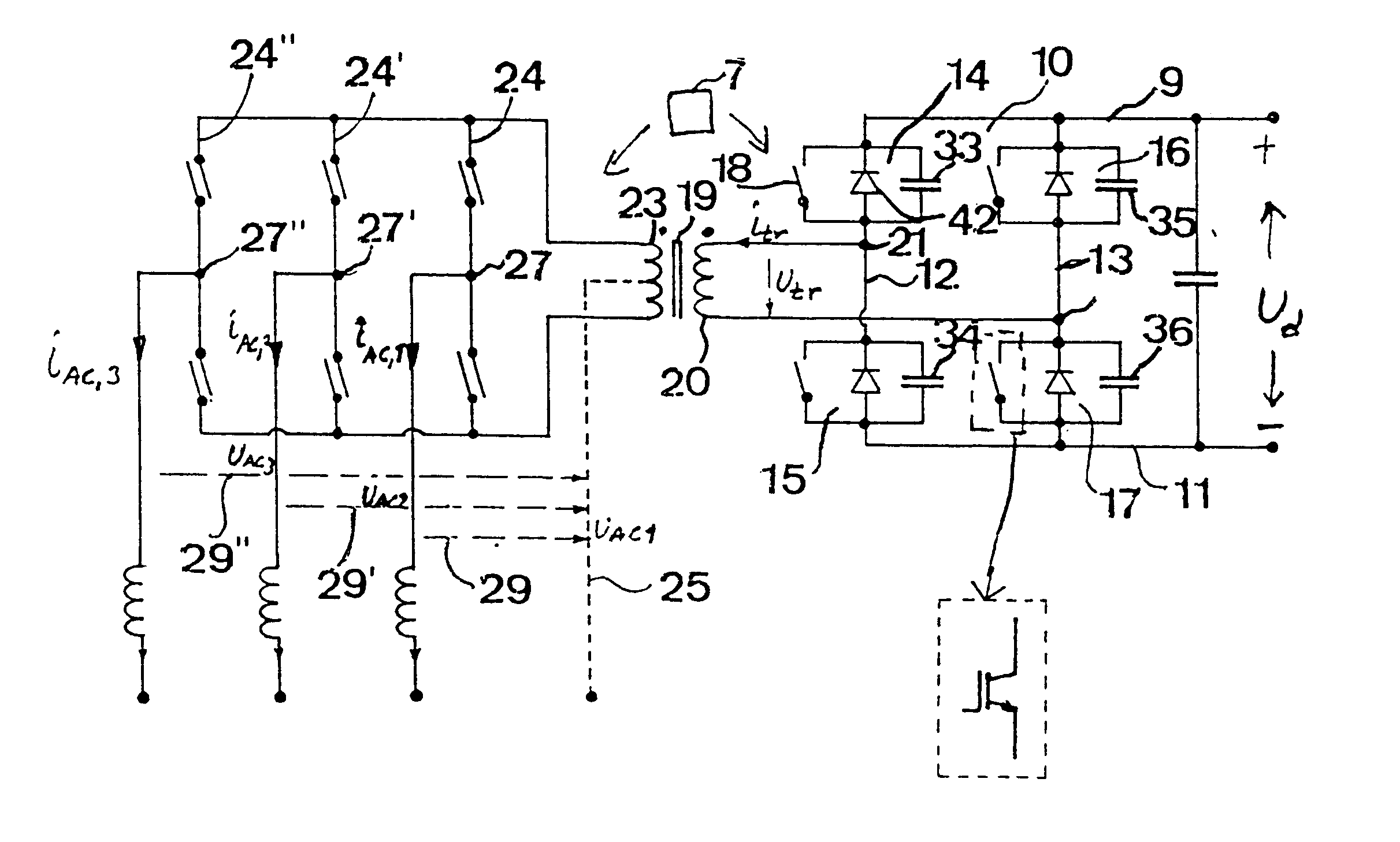
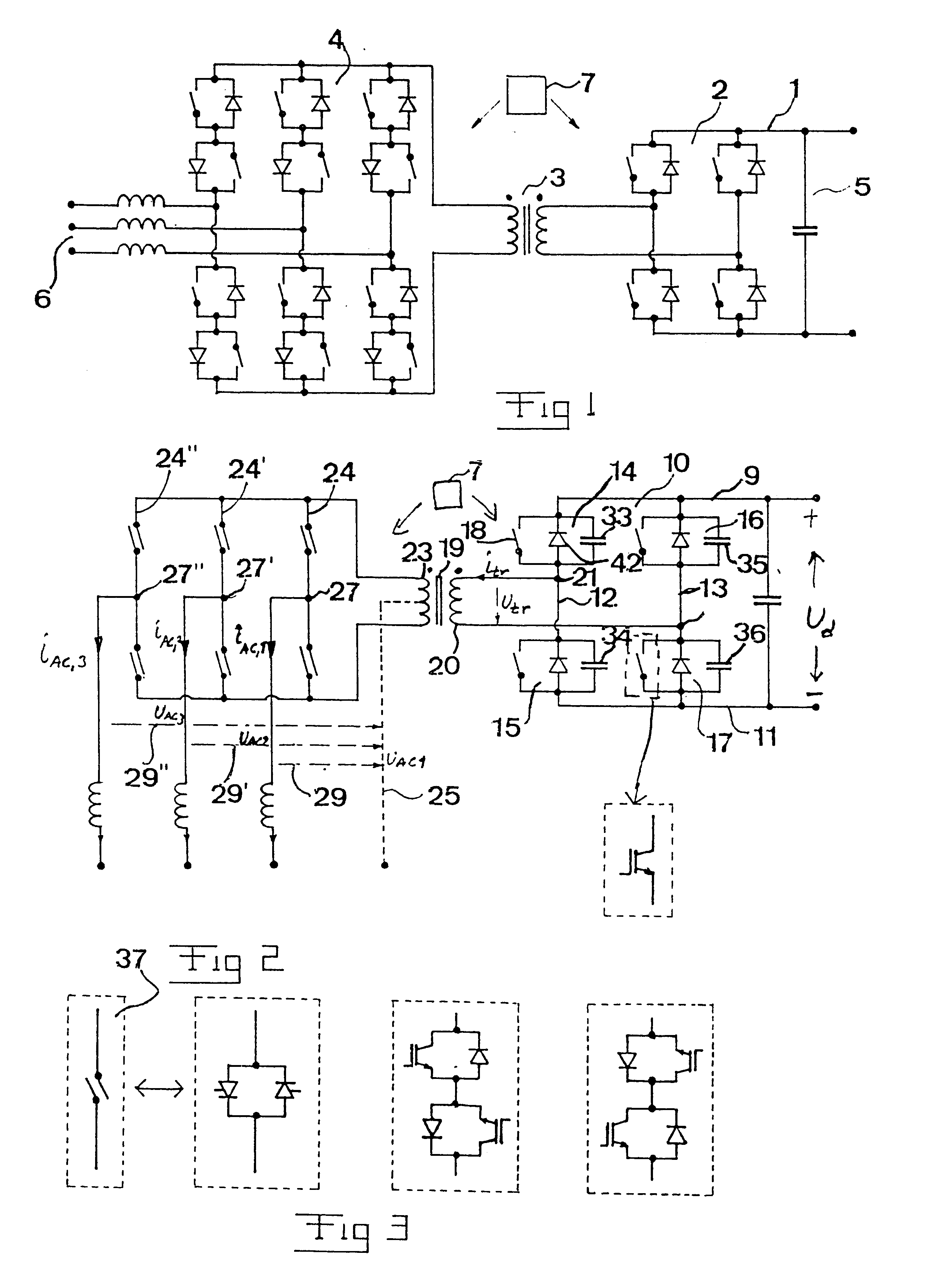
FIG. 2 illustrates an apparatus according to a preferred embodiment of the invention having a VSC-converter 8 with a direct voltage intermediate link 9 with a positive 10 and a negative 11 pole and two phase legs 12, 13 (1 and 2, respectively, in the formulas following) interconnecting the two poles and having two current valves 14-17 connected in series. Each current valve has one semiconductor device 18 of turn-off type, such as an IGBT, and a rectifying member 42, such as a rectifying diode, connected in anti-parallel therewith. A snubber capacitor 33-36 is connected in parallel with each said semiconductor device 18 and diode 42. A transformer 19 is with two opposite ends of a first winding 20 connected to an output 21, 22 each of the VSC-converter and with a second winding 23 (having a connection 25 to the midpoint thereof for grounding purposes) thereof with the opposite ends connected to the opposite ends of three phase legs 24, 24' and 24" (1, 2 and 3, respectively, in the f...


PUM


Abstract

An apparatus for converting direct voltage into three-phase alternating voltage and conversely comprises a VSC-converter (8) having a direct voltage intermediate link (9) and at least one phase leg (12, 13). Each current valve (14-17) of the phase legs has at least one semiconductor device of turn-off type and a rectifying member connected in anti-parallel therewith. A transformer (19) has two opposite ends of a first winding (20) thereof connected to an output (21, 22) each of the VSC-converter and a second winding (23) connected to a direct converter having at least three phase legs. Each of the current valves of the direct converter being able to conduct current and block voltage in both directions and to turn on by gate control. The midpoints (27, 27', 27'') of the phase legs of the direct converters are provided with phase outputs for forming a terminal for the alternating phase voltage between these phase outputs.

Description

FIELD OF THE INVENTION AND PRIOR ARTThe present invention is occupied with the problem to convert direct voltage into three-phase alternating voltage and conversely in all types of applications, such as in plants for transmission of electric power and for connecting three-phase electric machines to DC voltage loads and sources. Any ranges of voltages, currents and powers are conceivable.The invention relates more particularly to such an apparatus comprising a VSC-converter (VSC=Voltage Source Converter) having a direct voltage intermediate link with a positive and a negative pole and at least one phase leg interconnecting the two poles and having at least two current valves connected in series, each current valve having at least one semiconductor device of turn-off type and a rectifying member connected in antiparallel therewith, the apparatus further comprising a transformer with two opposite ends of a first winding thereof connected to an output each of the VSC-converter and with ...

Claims


Application Information

Patent Timeline
Patent Type & Authority Patents(United States)
IPC IPC(8): H02M5/02H02M5/297H02M7/219H02M7/48H02M7/483
CPCH02M5/297H02M7/219H02M7/483H02M2001/0048H02M2007/2195Y02B70/1408Y02B70/1491H02M7/4807Y02B70/10H02M1/0048H02M7/2195
Inventor NORRGA, STAFFAN
Owner ABB (SCHWEIZ) AG
Why Eureka
Try Eureka