Monitoring of connection between network devices in a packet-based communication system

a network device and communication system technology, applied in data switching networks, high-level techniques, frequency-division multiplexes, etc., can solve problems such as failure to complete a link between devices properly, insufficient quality of physical link between them, and degraded physical link quality

Inactive Publication Date: 2003-08-05
HEWLETT-PACKARD ENTERPRISE DEV LP
View PDF8 Cites 43 Cited by
  • Summary
  • Abstract
  • Description
  • Claims
  • Application Information

AI Technical Summary

Problems solved by technology

For example, although the devices which are connected by auto-negotiation may have the ability and the performance appropriate to a higher rate achieved by auto-negotiation, the physical link between them may not be of sufficient quality or may become degraded, so that the reliability and throughput of the connection is insufficient or is reduced.
However, a system of that kind, and systems of possibly the same general character, may in a variety of circumstances fail to complete a link between devices properly.
For example, both ends of a link may be capable of higher rate operation yet the physical link may not be capable of supporting the selected higher date rate.
For example, in the case of 10BASE-T / 100BASE-TX operation, it is possible that certain channel characteristics can cause a situation wherein auto-negotiation can complete, because it uses the robust 10BASE-T link pulse signaling system, and select a highest common denominator of 100 Megabits per second yet the channel is not of sufficient quality for the 100BASE-TX link to be established.
The 100BASE-TX linkOk requires a reliable presence of the received idle symbol stream and on a low quality link this may not be achieved.
Another difficulty that exists arises from the provision of a substandard link with a device which is capable of `smart auto-sensing` with a high quality receiver, connected to a far end device which has a low quality receiver and is not capable of `smart` auto sensing.
Notwithstanding the robustness of such a scheme, various situations can occur which may defeat the `smart` device.
In this situation the continuous auto-negotiation would still occur because it would be forced by the device that was unable to establish the link.

Method used


Image

  • Monitoring of connection between network devices in a packet-based communication system
  • Monitoring of connection between network devices in a packet-based communication system
  • Monitoring of connection between network devices in a packet-based communication system

Examples


Embodiment Construction

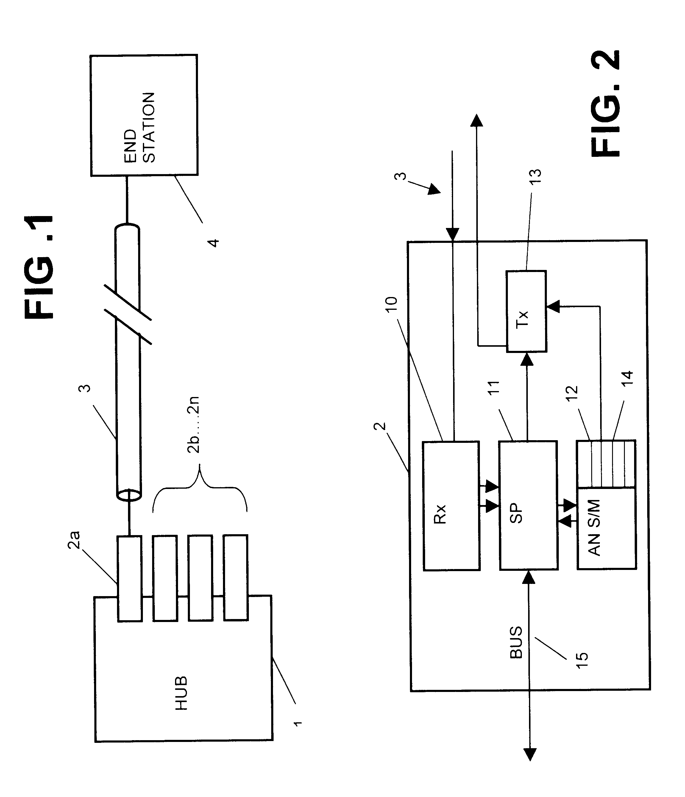
FIG. 1 and FIG. 2 illustrate schematically, as indicated previously, a hub connected to an end station and certain operational functions within a hub. The representation is schematic only, because hubs such as Ethernet hubs operating according to a dual standard such as 10 and 100 Megabits per second are well known in the art and the process of auto-negotiation is also well known, being defined in the aforementioned IEEE standard and fully explained in the aforementioned publication.

FIG. 1 illustrates therefore an Ethernet hub 1 having a plurality of ports 2a, 2b . . . 2n, in which port 2a is shown as connected by way of a cable connection 3 to another network station, particularly an end station such as a personal computer 4. The hub 1 may have many connections to other end stations but each of these is an independent point-to-point link.

FIG. 2 illustrates the physical layer associated with a port 2 which is connected to the physical link 3, which may for example by constituted by ...


PUM


Abstract

The invention concerns the establishment of the rate of transmission of data between two network stations by means of auto-negotiation. The execution of an auto-negotiation sequence by a state machine is counted and if the number of executions of the sequence exceeds a threshold, the auto-negotiation sequence is modified to establish a data rate lower than a previously negotiated rate. A particular example is described for use in accordance with IEEE standard 802.3. In a specific example, monitoring of the execution of the auto-negotiation sequence comprises counting the occurrences of a "page received' bit in an auto-negotiation expansion register.

Description

This invention relates to packet-based data communication networks and particularly an Ethernet network or similar network wherein data may be transferred between devices, particularly a hub and another network station such as a personal computer, at at least two different rates, the devices being able to establish a selected data rate by means of auto-negotiation. The invention is particularly though not necessarily exclusively intended for use with an auto-negotiation scheme as defined in IEEE 802.3, 1998 Edition, Clause 28.BACKGROUND TO THE INVENTIONAs switching and other technology has improved, the rate at which data may be transferred between network devices has increased. Currently there are various standards to which successive generations of network devices has been designed to operate. In particular a standard data rate of 10 Megabits per second has been partly supplanted by a standard of 100 Megabits per second and is expected to be supplanted by an even faster rate, 1 Gi...

Claims


Application Information

Patent Timeline
Patent Type & Authority Patents(United States)
IPC IPC(8): H04L5/14H04L1/00H04L12/56H04L29/06H04L29/08H04L12/26H04L12/939
CPCH04L1/0002H04L5/1446H04L29/06H04L43/0811H04L43/0847H04L43/16H04L12/2602H04L43/00H04L49/55Y02B60/31H04L69/24H04L69/324Y02D30/50H04L9/40
Inventor POULTER, ALAN RLAW, DAVID JCRAMPHORN, PAULBREWER, STEVENOVERS, PATRICK M
Owner HEWLETT-PACKARD ENTERPRISE DEV LP
Why Eureka
Try Eureka