Method and apparatus for establishing frame synchronization

a frame synchronization and frame technology, applied in the direction of electrical apparatus, synchronisation signal speed/phase control, digital transmission, etc., can solve the problems of increasing power consumption at the time of switching and heat generation due to this power consumption, expensive devices treating high-speed digital signals, and difficult to get devices

Inactive Publication Date: 2003-08-05
NEC CORP
View PDF6 Cites 4 Cited by
  • Summary
  • Abstract
  • Description
  • Claims
  • Application Information

AI Technical Summary

Problems solved by technology

Therefore, the device treating the high-speed digital signal becomes expensive, and it is difficult to get the device.
In the device treating the high-speed digital signal, the higher the speed of the digital signal is, the more the number of switchings per unit time increases, and the power consumption at the time of switching and heat generation due to this power consumption increases.
Therefore, cooling becomes necessary due to large ordinary power consumption and heat generation, and hence an apparatus becomes large.
On the other hand, the frame synchronous circuit becomes complicated in many cases and treats a high-spe

Method used


Image

  • Method and apparatus for establishing frame synchronization
  • Method and apparatus for establishing frame synchronization
  • Method and apparatus for establishing frame synchronization

Examples


first embodiment

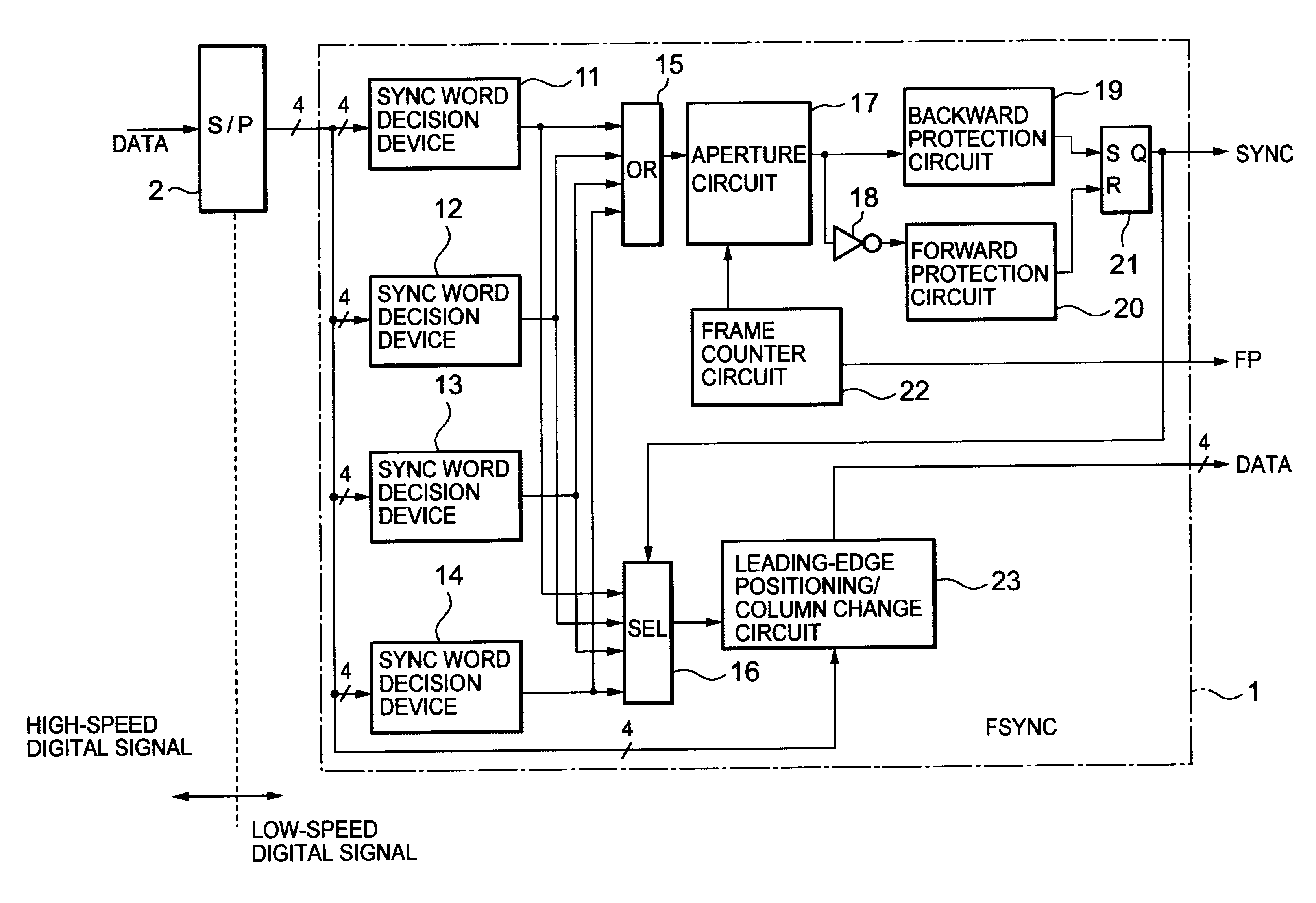
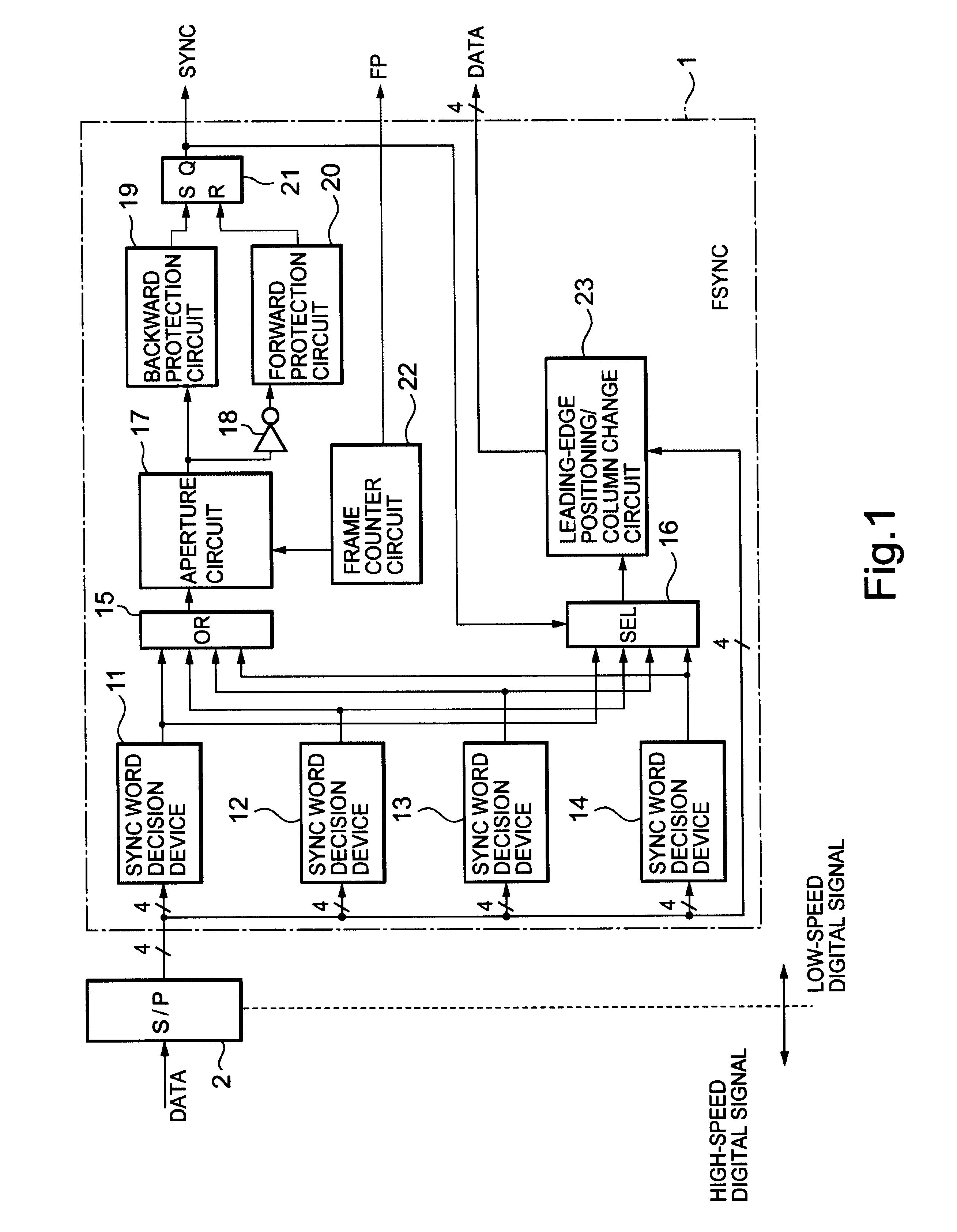
Next, embodiments of the present invention will be described with reference to drawings. FIG. 1 is a block diagram showing the configuration of a frame synchronous circuit according to the present invention. In FIG. 1, a frame synchronous circuit (FSYNC) 1 comprises synchronous word decision devices 11 to 14, an OR circuit (OR) 15, a selection circuit (SEL) 16, an aperture circuit 17, an inverter 18, a backward protection circuit 19, a forward protection circuit 20, a flip-flop circuit 21, a frame counter circuit 22, and a leading-edge positioning / column change circuit 23.

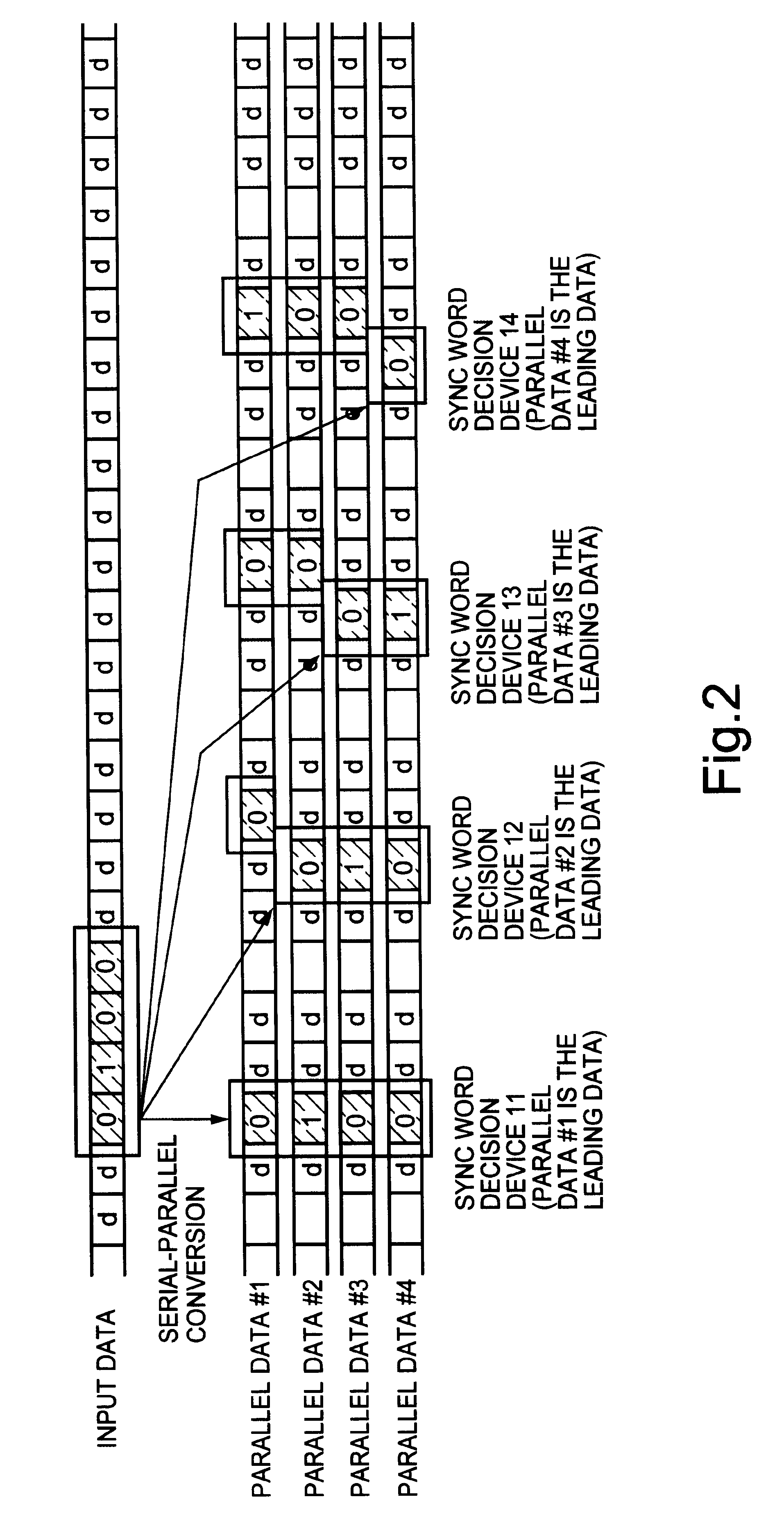
Here, it is assumed that four lines of low-speed digital signals, into which one line of a high-speed digital signal is serial-parallel-converted in a serial-parallel converter (S / P) 2, are inputted to the frame synchronous circuit 1 described above. Similarly, it is assumed that a sync word is composed of 4 bits.

The synchronous word decision devices 11 to 14 receive four lines of low-speed digital signals from the...

second embodiment

Against this, in the present invention, a frame synchronous circuit 3 decides after the establishment of synchronization into what kind of sync word the apparent sync word changes. Moreover, the frame synchronous circuit 3 disables the devices, which do not correspond to the apparent sync word, among the synchronous word decision devices 11 to 14, to output signals to the aperture circuit 17.

After the establishment of synchronization, the switch circuit 31 selecting one of the outputs of the synchronous word decision devices 11 to 14 selects an output of the selection circuit 16. The output of the selection circuit 16 is only one of the outputs of the synchronous word decision devices 11 to 14 that corresponds to the change of the apparent sync word. Therefore, in the forward protective operation, only one device among the synchronous word decision devices 11 to 14 is used.

Owing to this, when the out-of-step synchronization arises, a probability of erroneously detecting a sync word ...

third embodiment

Against this, in the present invention, a frame synchronous circuit 4 decides at the time of a first sync word decision into what kind of sync word the apparent sync word change. Moreover, the frame synchronous circuit 3 disables the devices, which do not correspond to the change of the apparent sync word, among the synchronous word decision devices 11 to 14, to output signals to the aperture circuit 17 at the time of performing backward protective operation according to the decision.

The switch circuit 31 selecting one of the output of the synchronous word decision devices 11 to 14 until a first sync word decision selects the output of the OR circuit 15. After the first sync word decision, the selection circuit 41 selects only one of the outputs of the synchronous word decision devices 11 to 14 that performed the first sync word decision. At the same time, the switch circuit 31 selects the output of the selection circuit 41. In addition, when the pull-in is succeeded, the switch cir...


PUM


Abstract

The present invention provides a frame synchronous circuit wherein the number of devices handling a high-speed digital signal is limited to the minimum without deteriorating frame pull-in time and an erroneous synchronization rate. For the sake of it, synchronous word decision devices decide frame synchronization from four lines of low-speed digital signals into which the high-speed digital signal is converted by a serial-parallel converter. An OR circuit synthesizes respective outputs of the synchronous word decision devices, and an aperture circuit applies an aperture to the output synthesized. A selection circuit fetches only one output corresponding to the change of the apparent synchronous word after establishment of synchronization. A frame counter circuit estimates a predetermined position of the next frame at the time of applying a narrow aperture. A leading-edge positioning/column change circuit performs leading-edge positioning and column change of data to the output of the selection circuit.

Description

1. Field of the InventionThe present invention relates to method and apparatus for establishing frame synchronization, and in particular, to method and apparatus for establishing frame synchronization for a high-speed digital signal in a digital signal transmission apparatus.2. Background of the InventionHeretofore, a frame synchronous circuit, as shown in FIG. 6, comprises a synchronous word decision device 61, an aperture circuit 62, an inverter 63, a backward protection circuit 64, a forward protection circuit 65, a flip-flop circuit 66, and a frame counter circuit 67.The synchronous word decision device (hereinafter, this is called a decision device) 61 decides frame synchronization by comparing an SW (sync word), which is added in a frame inputted, with a sync word held in its own circuit. The aperture circuit 62 applies an aperture to an output of the decision device 61. The frame counter circuit 67 estimates a predetermined position of a frame, which will be received subseque...

Claims


Application Information

Patent Timeline
IPC IPC(8): H04J3/06H04L7/08
CPCH04J3/0608
Inventor KUBOTA, ATSUHIRO
Owner NEC CORP
Why Eureka
Try Eureka