Adjustable bone stabilizing frame system

a frame system and adjustable technology, applied in the field of external fixation or adjustable bone stabilizing frame systems, can solve the problems of inability to easily adjust the frame construction during its assembly, repeated tightening and loosening of the clamps, and the inability of prior art frame systems to be securely clamped, etc., to achieve quick and easy assembly

Inactive Publication Date: 2003-09-02
ZIMMER INC
View PDF20 Cites 102 Cited by
  • Summary
  • Abstract
  • Description
  • Claims
  • Application Information

AI Technical Summary

Benefits of technology

By employing the present invention, all of the difficulties and drawbacks found in the prior art are eliminated and a fully external fixation or adjustable frame structure is provided which is capable of being quickly and easily assembled in any desired configuration. In addition, the frame structure of the present invention is retained in any assembled configuration in order to...

Problems solved by technology

Although wide variety of frame structures and clamp systems have been used for this purpose, one common problem existing with most prior art stabilizing frame constructions is the inability to allow the frame construction to be easily adjustable during its assembly.
However, during the creation of the frame structure, which must be maintained in a precise orientation in order to assure that the bone fracture is precisely aligned for healing, these prior art frame systems have been found to be incapable of being retained in a desired position unless securely clamped.
As a result, repeated tightening and loosening of the clamps is required before the precisely desir...

Method used


Image

  • Adjustable bone stabilizing frame system
  • Adjustable bone stabilizing frame system
  • Adjustable bone stabilizing frame system

Examples


Embodiment Construction

By referring to FIGS. 1-24 along with the following detailed discussion, the construction and operation of the external fixation or adjustable frame system of the present invention can best be understood. Although the following disclosure fully details different embodiments of the present invention, these embodiments are provided as preferred examples of the present invention. Consequently, it is to be understood that these embodiments are provided for exemplary purposes only, and are not intended as a limitation of the present invention.

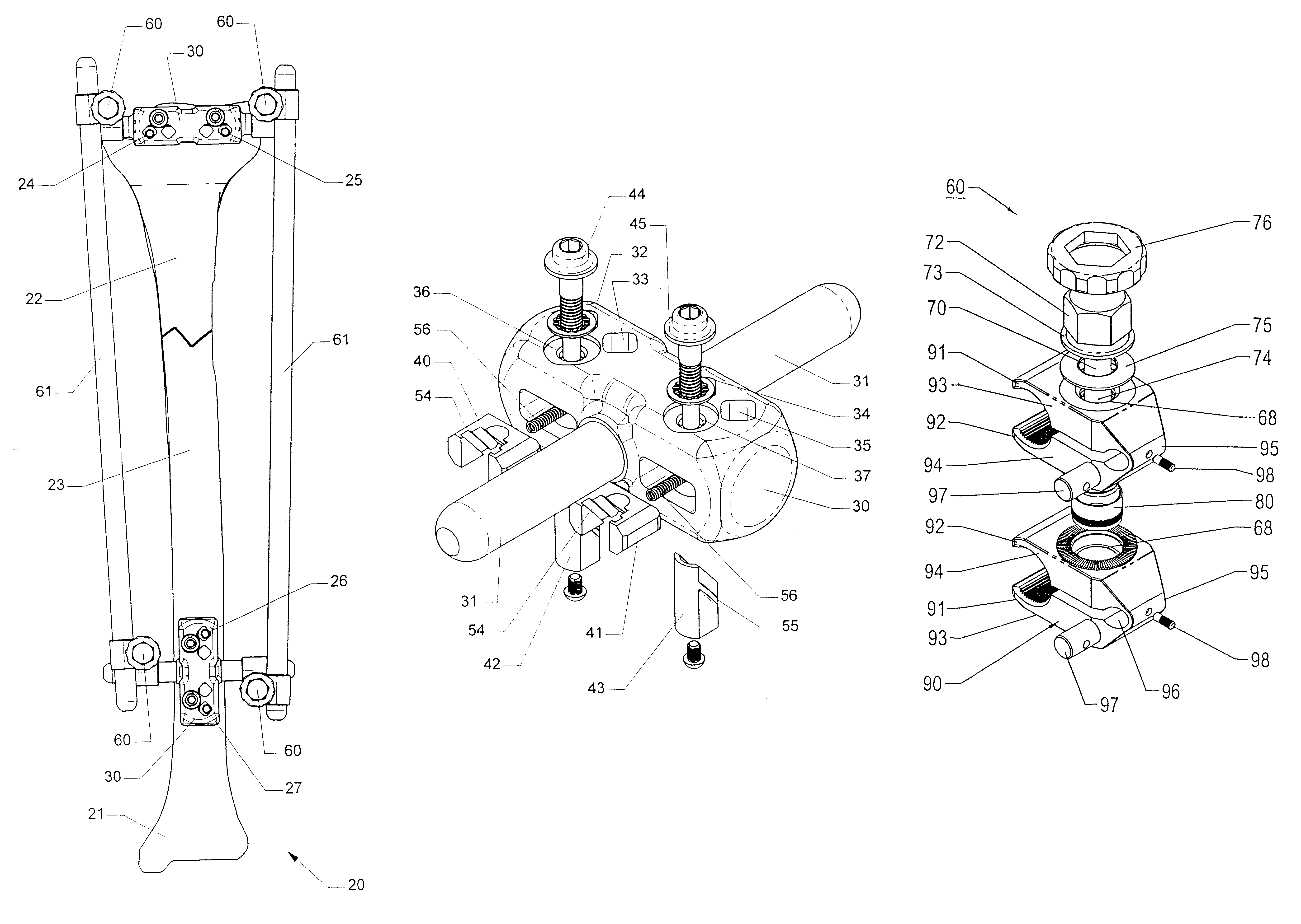
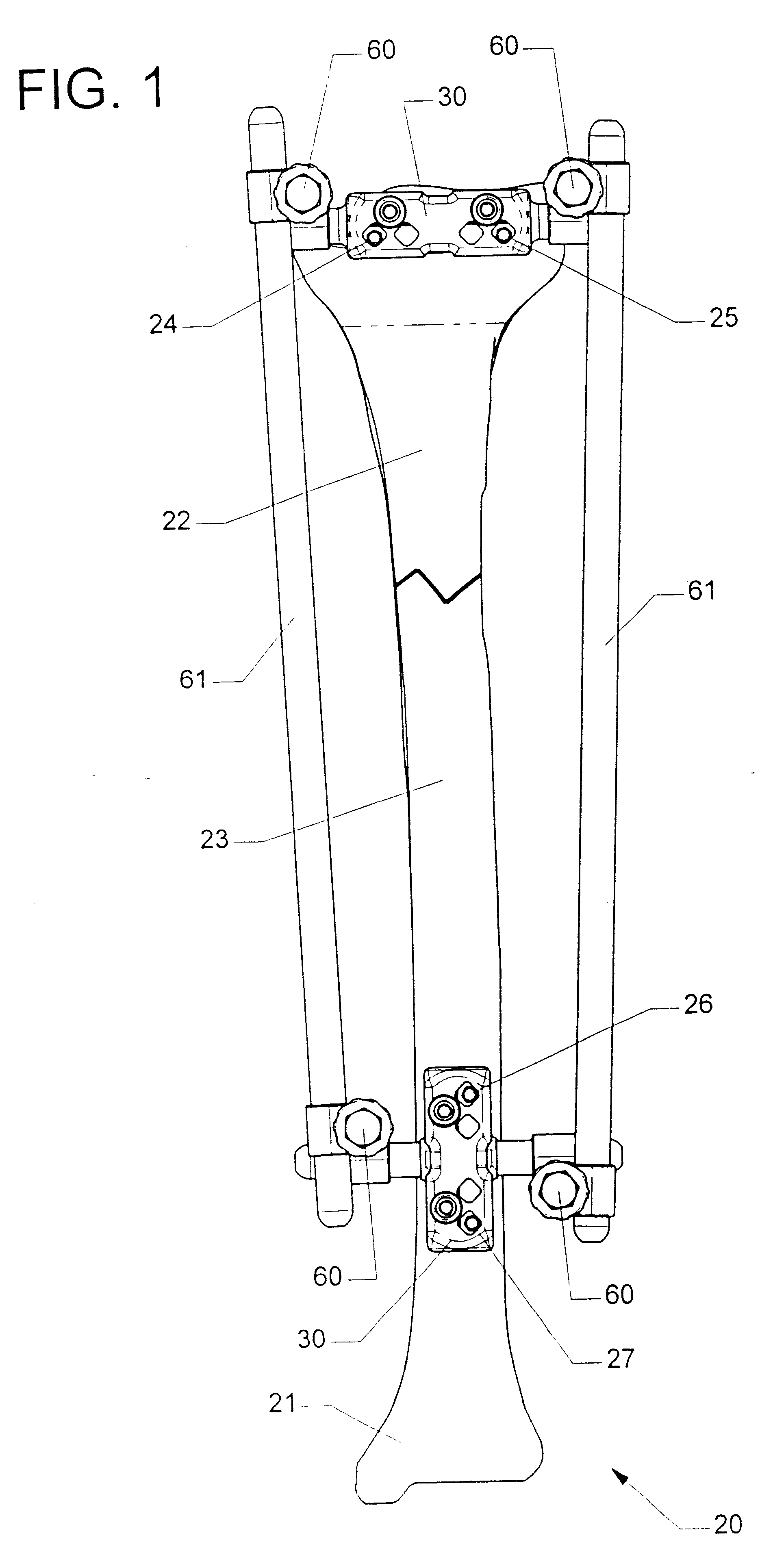
In FIG. 1, one embodiment of the external fixation or adjustable frame system 20 of the present invention is depicted, securely mounted to broken leg bone 21 or a tibia for maintaining the components of the broken bone in the precisely desired position for healing. As depicted, leg bone 21 has a transverse break, forming upper part 22 and lower part 23.

In order to set and maintain bone 21 in the desired configuration for healing, anchor pins 24 and ...


PUM


Abstract

By providing components securable to anchor pins or screws of different diameters as well as providing clamps which hold associated pins in any position during adjustments, an external fixation or adjustable frame structure is provided which is capable of being quickly and easily assembled in any desired configuration. In the present invention, the frame structure is retained in any assembled configuration in order to allow final adjustments to be made, prior to the final securement of the frame assembly in the precisely desired configuration by closure of each clamp member. In this way, an entire frame assembly is capable of being constructed, adjusted, and readjusted in order to assure each component is oriented in the precisely desired position prior to final closure of the clamping members. In one preferred embodiment, the clamping members employed in the frame structure of the present invention incorporate friction pins internally mounted in each clamp which engages the rod member once this rod is inserted into the jaws of the clamp. In this way, any rod member inserted into the clamping jaws contacts the surface of the jaws and the friction pin, preventing the rod member from sliding or moving relative to the clamp. In addition, by incorporating a uniquely constructed, moving wedge plate that is adjustably engageable with any cooperating anchor pin, secure affixation of the mounting member with the anchor pins of any diameter is easily achieved, regardless of the orientation configuration, or diameter of the anchor pin.

Description

TECHNICAL FIELDThis invention relates to external fixation or adjustable bone stabilizing frame systems and, more particularly, to frame assemblies employed with broken and / or fractured bones for retaining and holding the bone and in a desired configuration for resetting.BACKGROUND ARTThe use of external fixation or stabilizing frames for retaining broken or fractured bones in a particularly desired orientation or configuration is widely known and commonly employed. However, in most typical prior art external frame constructions, particularly frame constructions employed to stabilize broken or fractured bones, a variety of clamps and holding rods are employed to enable the surgeon to position the broken / fractured bones in a precisely desired position or orientation, and then allowing the bone to be retained in that position or orientation for healing.Although wide variety of frame structures and clamp systems have been used for this purpose, one common problem existing with most pri...

Claims


Application Information

Patent Timeline
IPC IPC(8): A61B17/60A61B17/64
CPCA61B17/6466A61B17/6458A61B17/645
Inventor WINQUIST, ROBERT A.BOGERT, ROYHUMMEL, CHARLESSEATON, JAMESNELSON, JAMES
Owner ZIMMER INC
Why Eureka
Try Eureka