Method and apparatus for simple IP-layer bandwidth allocation using ingress control of egress bandwidth

a technology of ingress control and egress bandwidth, applied in the field of switch devices, can solve the problems of inability to economically sound, transfer rate, and further complicated output buffer models, and achieve the effect of limiting the possibility of congestion

Inactive Publication Date: 2003-09-30
NORTEL NETWORKS LTD
View PDF4 Cites 143 Cited by
  • Summary
  • Abstract
  • Description
  • Claims
  • Application Information

AI Technical Summary

Benefits of technology

An object of this invention is to provide a novel switch device capable of controlling the transport of data units, such as IP data packets, between the input ports and the output ports of the switch to limit the possibility of congestion that can arise at the output port level of the switch.
Data insertion throttling can be made particularly when traffic of a minimum guaranteed bandwidth with possibility of overflow is being sent from one node to another node. This class of traffic, commonly referred to C2 is guaranteed a minimum bandwidth and if excess bandwidth is required, more bandwidth can be made available if it is available. In this case the throttling to free more time slots can be effected by effecting insertion of data packets in a path at a rate that does not exceed the minimum guaranteed bandwidth allocated to the traffic class. If, on the other hand, the downstream nodes do not use all the free time slots available, then the node can increase the insertion rate so that excess C2 class traffic can be passed.

Problems solved by technology

The problem with Egress based control of bandwidth is that ideally the output would like to take traffic from all ports as soon as it arrives.
For large values of N (number of input ports) and input bandwidth rates, this is not economically sound and lower transfer rates are used.
The output buffered model is further complicated when multi-link trunks (logical links) are employed and the bandwidth allocation must be satisfied over the total bandwidth of the logical output port.

Method used


Image

  • Method and apparatus for simple IP-layer bandwidth allocation using ingress control of egress bandwidth
  • Method and apparatus for simple IP-layer bandwidth allocation using ingress control of egress bandwidth
  • Method and apparatus for simple IP-layer bandwidth allocation using ingress control of egress bandwidth

Examples


Embodiment Construction

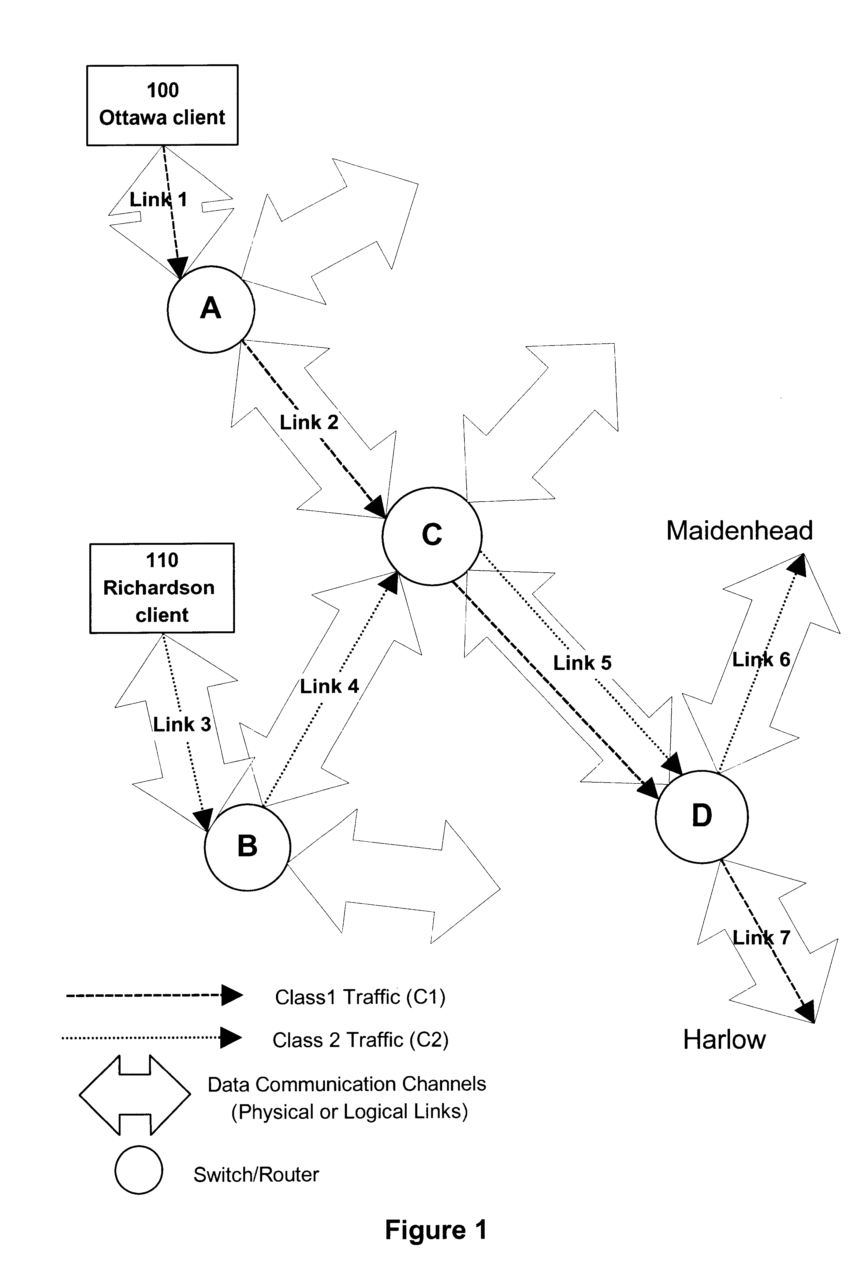
FIG. 1 illustrates an example of a situation where two different classes of traffic travel through a data communications network that has adopted the Internet Protocol (IP) for its internetwork procedures. The two different classes of traffic present are C1 and C2. For a given logical egress port, C1 traffic is always able to use up the reserved amount of allocated bandwidth if it has traffic to send; however, this class is never allowed to use more than the reserved amount even if there is bandwidth available. As to the C2 class, for a given logical egress port, C2 traffic is always able to use up the reserved amount of bandwidth if it has traffic to send; however, if it has more traffic to send it can compete equally with other permitted classes for any available bandwidth, up to a certain maximum amount. In the case of FIG. 1, an Ottawa client 100 is ending traffic of class C1 (reserved bandwidth without overflow) to Harlow, whereas a Richardson client 110 is sending traffic of c...


PUM


Abstract

The present invention relates to a switch for processing data units, such as IP data packets. The switch can be implemented as a router that includes a plurality of input ports, a plurality of output ports and a switch fabric capable of establishing logical pathways to interconnect a certain input port with a certain output port. A characterizing element of the router is its ability to control bandwidth usage on a basis of a logical pathway. This prevents congestion to occur in the switch fabric and also at the level of the output ports. For every active logical pathway the router sets-up a bandwidth control mechanism including at least one queue to hold data units received at an input port. The bandwidth control mechanism performs an accounting operation to determine the average bandwidth usage and if less than a threshold requests for releasing data units in the switch fabric are sent to the switch fabric controller. When the threshold is exceeded the bandwidth control mechanism stops sending requests for service to the switch fabric controller. The system also supports priorities. Instead of stopping the issuance of signals requesting release of data packets the priority level of the queue (reflected in a priority field in the signal requesting release of a data packet) changes from HI to LO. The switch fabric controller is designed to recognize priority requests and will accept LO priority requests only when there are no other HI priority requests pending. The present invention also provides a data transport device which includes a plurality of nodes interconnected by a physical link that establishes two ring-shaped paths on which data is transported on opposite directions. Each node is capable of sending a control message to the upstream node to advise the upstream node of the data carrying requirements of the node at which the message has originated. The upstream node can then throttle the introduction of data in the paths to preserve capacity that can be used by the downstream nodes.

Description

The present invention relates to the field of data communication networks.The following paragraphs give definitions of terms relevant to this document:Physical Link: A single point-to-point serial transmission link between two nodes in a network (such as between two routers or between a router and a host machine).Physical Output Port: The output port of a switch, such as a router that supports at least one physical link.Logical Link: A point-to-point traffic path between two switches that is composed of multiple parallel physical links and appears from a routing point of view to be one link.Logical Output Port: The collection of physical output ports that support the physical links of a logical link.Logical Pathway: A pathway internal to a switch connecting an input port to an output port.Internet Protocol (IP): A library of routines called on by various network communications applications. IP is responsible for transporting packets of data from node to node. It forwards each packet...

Claims


Application Information

Patent Timeline
Patent Type & Authority Patents(United States)
IPC IPC(8): H04L12/56H04L12/24
CPCH04L12/5693H04L41/0896H04L47/10H04L47/12H04L47/50
Inventor CHAPMAN, ALAN STANLEY JOHNKUNG, HSIANG-TSUNG
Owner NORTEL NETWORKS LTD
Why Eureka
Try Eureka