1)--The extraordinary complexity of keypads on many "universal" and OEM remote controls confuses the viewer, especially when the viewer is elderly, visually or physically handicapped, bewildered by medications or intoxicants, or simply trying to use the
remote control in a dimly lit viewing room;
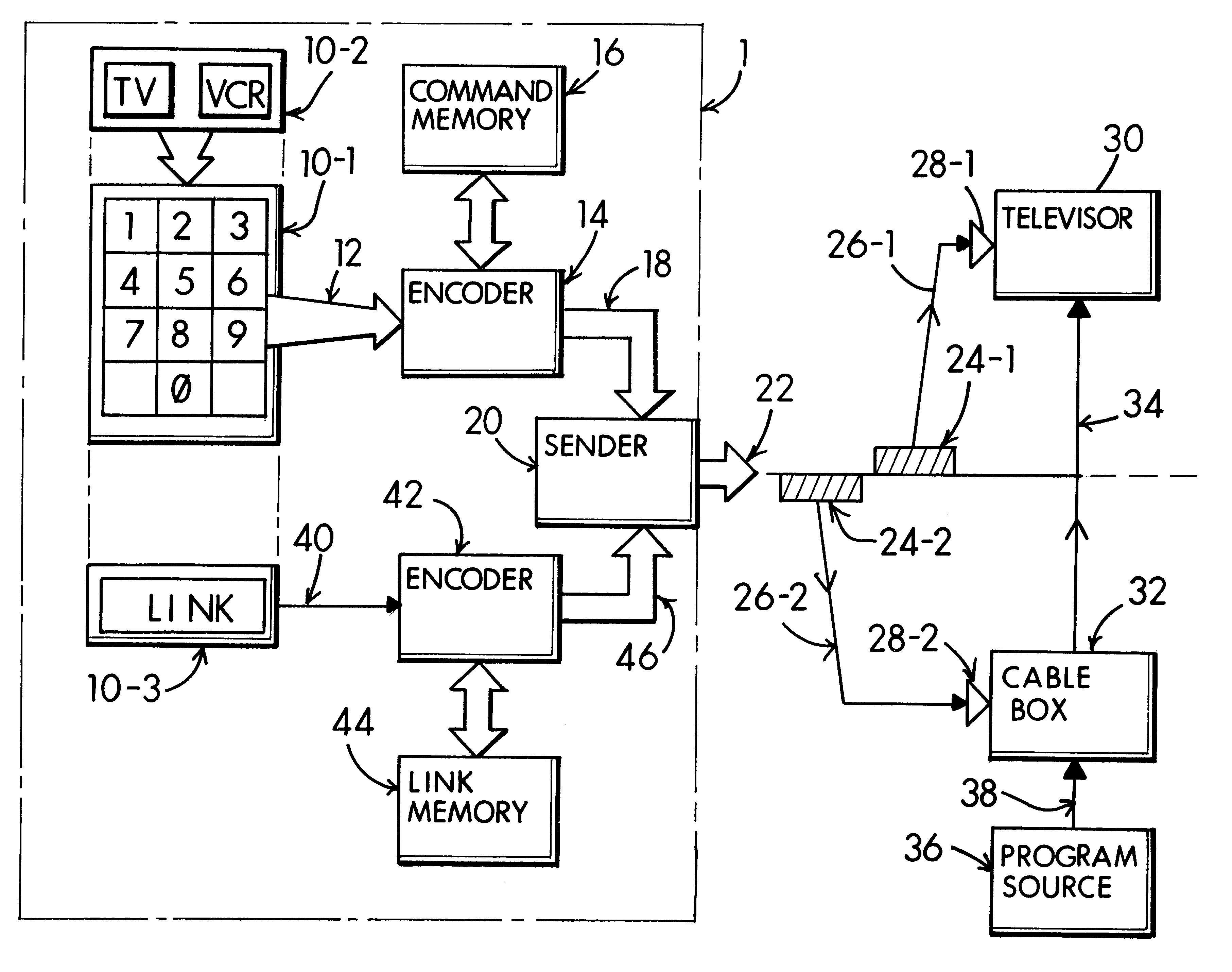
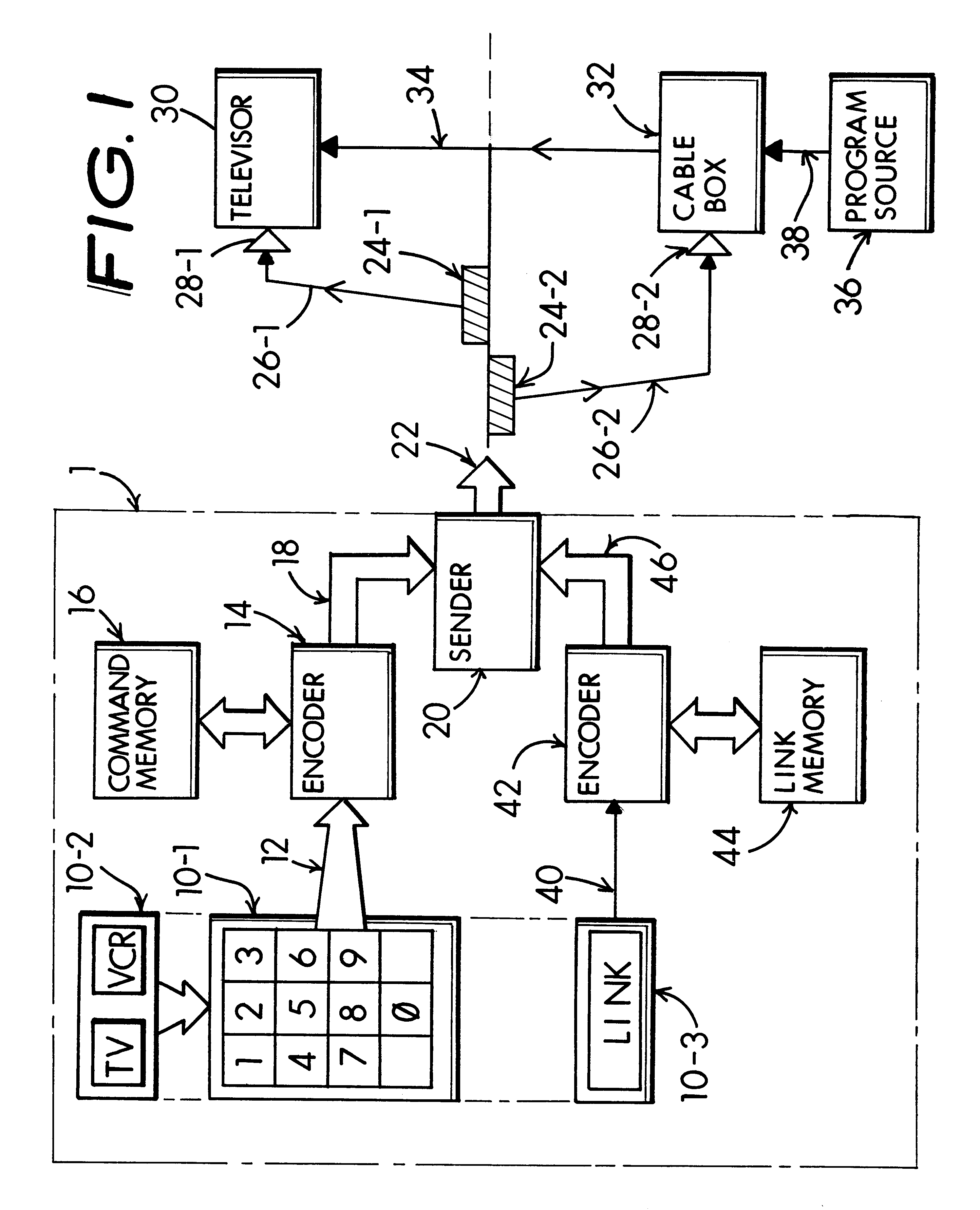
2)--Several different "original equipment" remote controls are needed to operate the television and VCR-
machine or cable box. For example, one remote control is needed to turn the televisor on and off and adjust volume, or other viewing parameters such as brightness, etc. A second remote control is then needed to select a preferred incoming program channel on the cable box, VCR-
machine or whatever other accessory device is involved. Obviously this requirement for more than one remote control can, in and of itself, lead to
confusion and of course resetting the intermediate channel selection for the televisor to a "wrong channel", say rather than the necessitous channel 3 is quite likely to occur. Most commonly this happens merely because the viewer picks-up the wrong remote control and begins to enter channel changes which for example may mistakenly tune the televisor to an erroneous channel other than the necessitous channel 3 (or channel 4).
3)--A handheld "universal" remote controller may be used which is intended to replace two or more manufacturer's original equipment remote controls. A typical universal remote control, such as a RCA "SystemLink-4" Model RCU1400VP, includes four buttons marked TV, VCR, CABLE and AUX. Pressing the appropriate button places the remote controller in each of the available
modes in order to operate with the associated televisor or accessory apparatus. Other remote controls, such as the SANYO "
Moonlight" Model RMT-U100 and the Universal
Electronics Inc. "One-For-All" Model 2060 operate in a similar manner and thus they afford equivalent mechanisms for introducing
user error. Quite simply it is the obvious likelihood that pressing the "wrong buttons" may introduce the "wrong operation". Extend this to the usual real life setting found in a
dark room, maybe including distractions. Add eyesight limitations and age issues and every chance for mistaken operation is present. The result is attempted operation of a cable box or VCR-
machine with a televisor, while the televisor is set to the wrong intermediate channel choice. The combinatorial consequence is mixed up operation, wrong channel selections or perhaps just a snowy screen with no picture at all.
While "resetting" the televisor back to the necessitous interlink channel 3 (sometimes called the "video channel") is an obvious technique for overcoming this problem, it is not a practical answer in many everyday situations.
For example, when a spectator sports event (e.g., a football game or the like) is underway or when a movie or similar program is about to begin, the erroneous mistuning of the televisor to the wrong intermediate channel setting (e.g., something other than channel 3) can lead to an onset of frenzy in a frantic attempt to "get everything running again" without lapse of program content.
As a result, the viewer may miss an essential portion of his program, such as a significant "play" in a football game, a "knockout punch" in a boxing match, a news item at the beginning of a news program, or a revealing sequence in a movie plot.
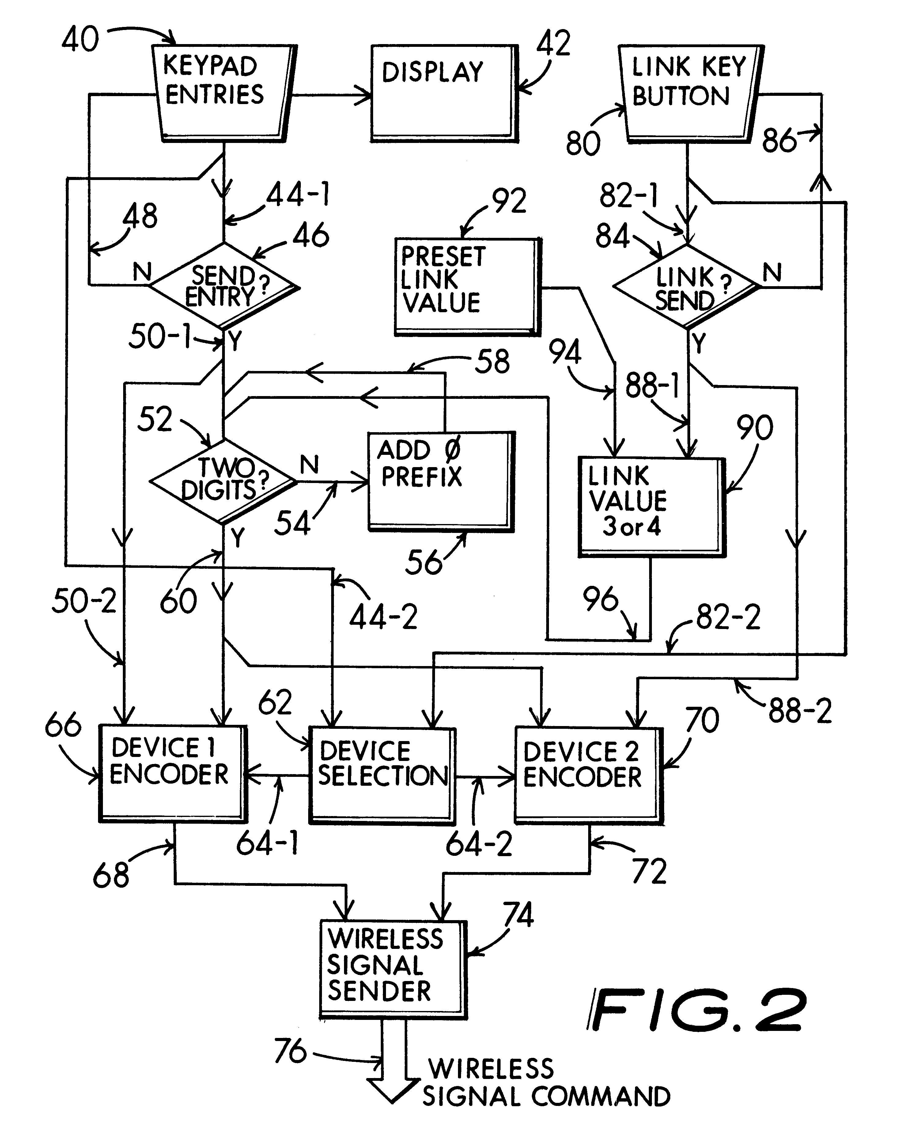
A selection of a specific combination of various devices does not conform with the usual practice of "matching channels".

