Method for concealing error

a technology of error detection and error detection, applied in the field of moving picture compression/decompression system, can solve the problems of continuous affecting the frame following, loss of all information in the slice with the error, and loss of a considerable portion of picture information

Inactive Publication Date: 2003-10-21
LG ELECTRONICS INC
View PDF12 Cites 109 Cited by
  • Summary
  • Abstract
  • Description
  • Claims
  • Application Information

AI Technical Summary

Problems solved by technology

When an error is generated in such a slice, all information in the slice with the error is lost.
In such case, an error in a bit of a bit stream results in the loss of a considerable portion of the picture information and continuously affects the frames following.
Accordingly, a severe deterioration in picture quality results when a decoder decodes a bit stream with an error.
Although this method is relatively simple and can quickly compensate a lost block, the accuracy of the compensated block is not high.
The temporal prediction concealing method especially results in low performance when there is fast motion or irregular motion between two continuous frames.
Although performance is satisfactory when there is no large change in pixel values across the boundary, the block boundary matching does not result in satisfactory performance at the edge or corner of the picture.
Moreover, for interlaced sequence, the conventional methods result in poor performance because spatial correlation is low between fields having different parities.
Especially, when there is a scene change, the visual picture quality deteriorates significantly.
However, such interpolation requires an apparatus for extracting and distinguishing each direction component of the edge, and requires a significant amount of calculation as compared to the conventional linear interpolation filtering.
However, a great amount of calculation at the receiver is required.
Particularly, when image sequences have a strong temporal correlation, the performance of the spatial prediction concealing method is inferior to that of the temporal prediction concealing method.

Method used


Image

  • Method for concealing error
  • Method for concealing error
  • Method for concealing error

Examples


Embodiment Construction

Reference will now be made in detail to the preferred embodiments of the present invention, examples of which are illustrated in the accompanying drawings.

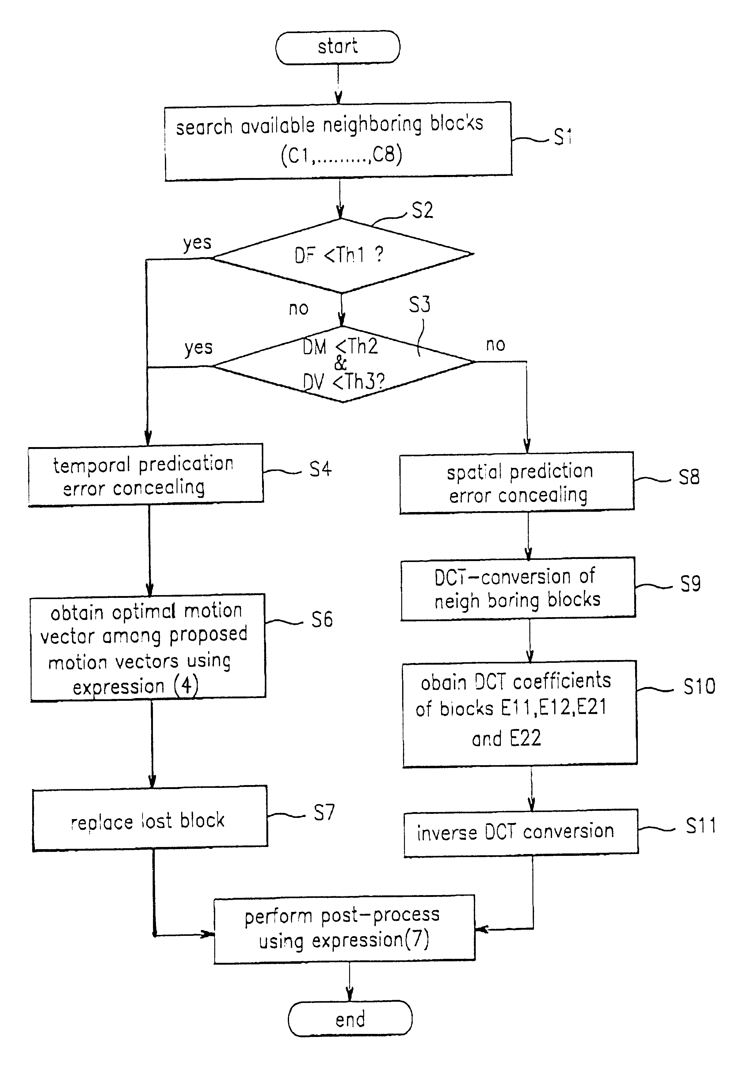
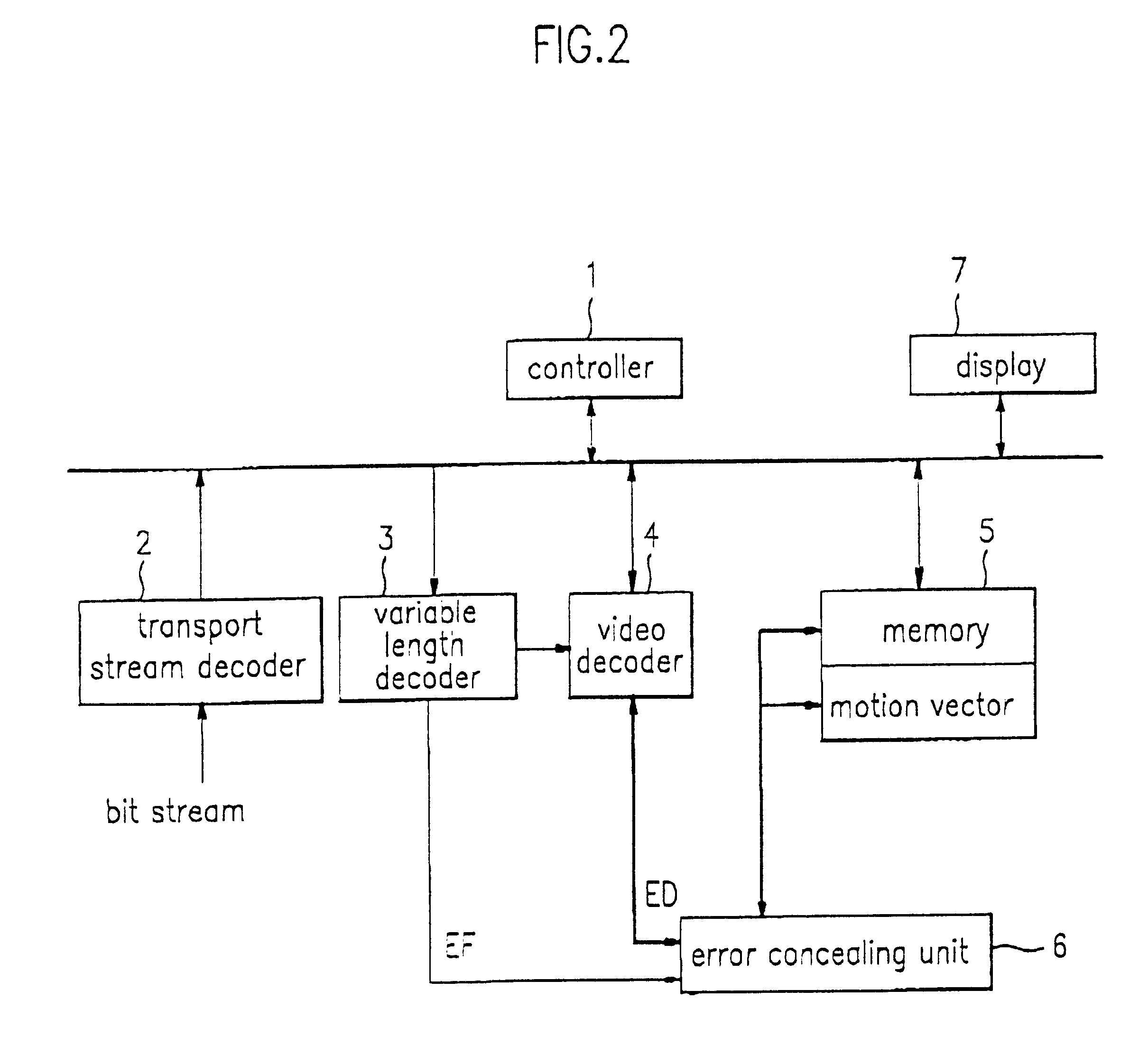
FIG. 2 is a block diagram of an error concealing apparatus according to the present invention including a controller 1 which controls the operation of the entire circuit; a transport stream decoder 2 which decodes a bit stream according to a control signal from the controller 1; a variable length decoder 3 which decodes the transport stream decoded by the transport stream decider 2 in a variable length and adds an error flag when an error is generated; a video decoder 4 which decodes the signal decoded by the variable length decoder 3 into a video signal, stores the video signal in a memory 5, and displays the video signal through a display 7; and an error concealing unit 6 which conceals and compensates an error according to the error flag inserted by the variable length decoder 3.

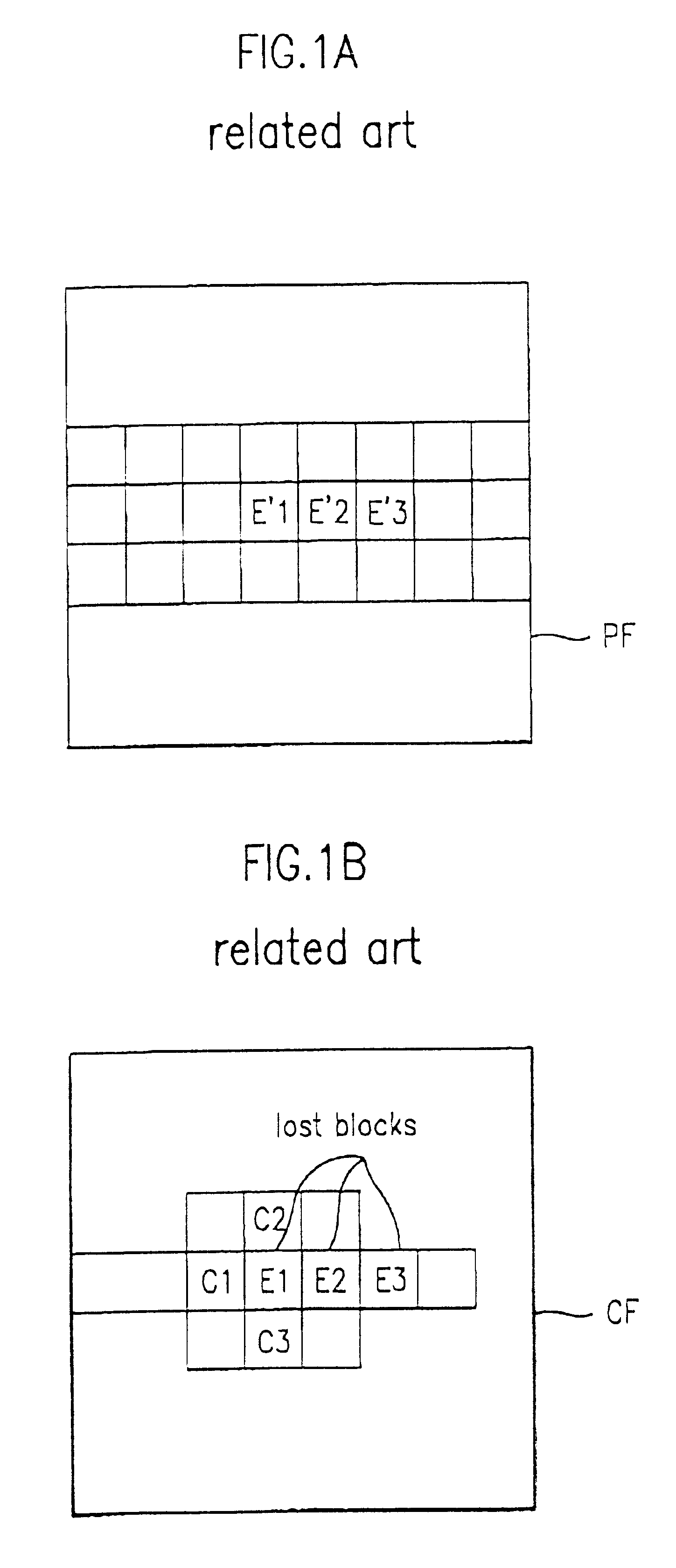
As discussed above, a picture is divided, into ma...


PUM


Abstract

A moving picture compression / decompression system utilizes a method for concealing errors in a received picture. A macro block, lost due to an error, is compensated using either a temporal or spatial prediction method, depending upon the type of frame and the characteristics of the picture. Thus, the displayed picture quality can be significantly improved.

Description

1. Field of the InventionThe present invention relates to a moving picture compression / decompression system and more particularly to a method for concealing errors in a moving picture compression / decompression system.2. Discussion of Related ArtUtilizing digital signal processing technology, many systems have been proposed to compress and transmit a large amount of moving picture information through a transmission channel of a limited bandwidth. In moving picture standards such as MPEG, H.261 and H.263, re-synchronization due to channel errors is performed in units of a slice. Each slice consists of a plurality of macro blocks and each macro block is the unit for motion compensation decoding. A single frame generally includes many slices depending upon the size of an image. When an error is generated in such a slice, all information in the slice with the error is lost.Also, moving picture coding methods use both variable length coding and motion compensation coding. In such case, an...

Claims


Application Information

Patent Timeline
Patent Type & Authority Patents(United States)
IPC IPC(8): H04N7/36H04N7/34H04N7/32H04N7/68H04N7/64H04N7/26H04N19/895H04N7/24
CPCH04N19/50H04N19/176H04N19/895H04N19/593H04N19/51H04N19/142H04N19/625
Inventor KIM, EUNG TAE
Owner LG ELECTRONICS INC
Why Eureka
Try Eureka