Unit ventilator

a ventilator and unit technology, applied in the field of unit ventilators, can solve the problems of need for disassembly, longer downtime of ventilating apparatus, and higher than desired equipment service cos

Inactive Publication Date: 2003-10-28
AIRTEX MFG PARTNERSHIP
View PDF24 Cites 32 Cited by
  • Summary
  • Abstract
  • Description
  • Claims
  • Application Information

AI Technical Summary

Problems solved by technology

While such apparatus of heretofore known design and construction may function acceptably, a problem occurs when it is necessary to service and repair or replace one or more of the apparatus components.
This problem results from the need for disassembly from the cabinet framing structure of the respective elements of the ventilator apparatus in order, first, to obtain access t

Method used


Image

  • Unit ventilator
  • Unit ventilator
  • Unit ventilator

Examples


Embodiment Construction

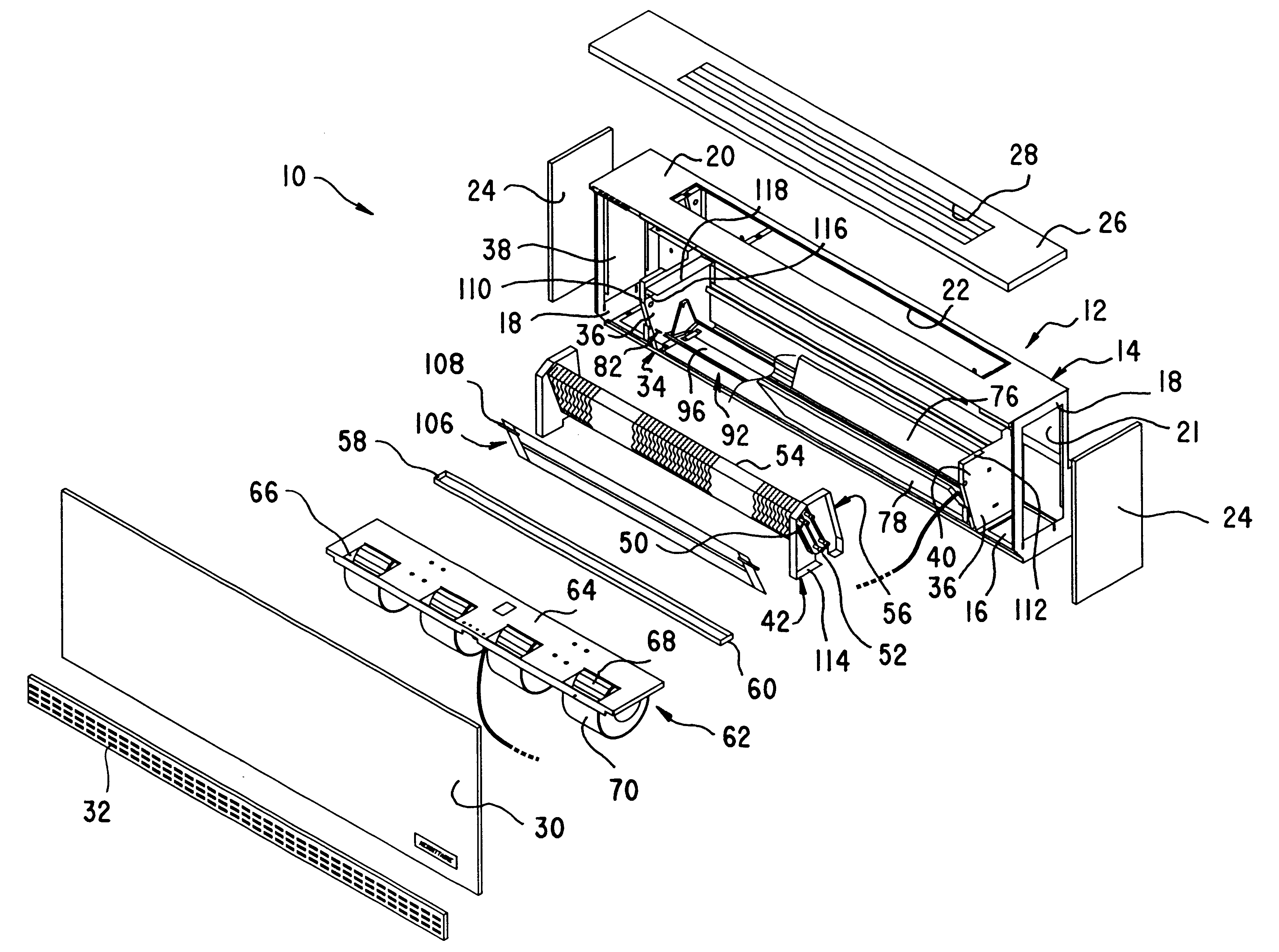
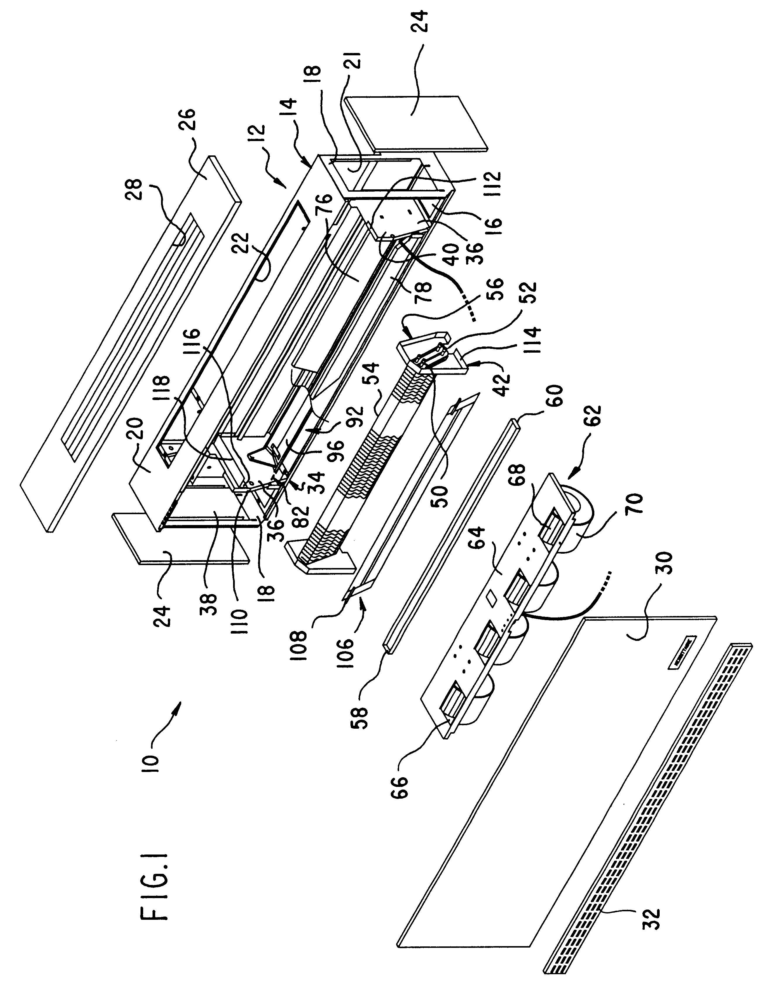
With particular reference to the drawings wherein like reference numerals designate like parts throughout the respective views, there is shown an exploded representation of a unit ventilator 10 according to the present invention. It includes a main chassis 12 providing a primary frame 14 which includes an elongated base 16, end plates 18 upstanding from opposite ends of the base, and a top plate 20 containing an air discharge opening 22 extending between, and joining, the upper ends of the end plates. Panels including end panels 24 and top panel 26 cover the end and top plates of the frame structure to form a cabinet of generally rectangular polyhedronal shape, with the top panel 26 containing a louvered opening 28 that overlies and communicates with the opening 22 in top plate 20 to form an air discharge opening from which processed air is discharged into the ventilated space. Front panel 30 is adapted by appropriate fastenings (not shown) for easy assembly to, and removal from, th...


PUM


Abstract

A unit ventilator is disclosed wherein, in order to facilitate service and repair of the ventilator and/or its component parts, such parts are mounted for ease of access and of detachment from, or assembly to, the system. Elemental system parts, such as the blower assembly, the heat transfer coil assembly, the condensate discharge pan and the air filters are designed and arranged so as to be assembled and/or disassembled from the system rapidly and with minimum use of tools.

Description

The present invention relates to unit ventilators having a blower or fan and being operative for discharging either cooled or heated air into a space to be ventilated. More particularly, the present invention concerns a unit ventilator system wherein, due to element design and system arrangement, components are readily removable and installable in order to facilitate replacement or service of the components and to reduce to a minimum the time, effort and cost attendant with system service and maintenance.BACKGROUND OF THE DISCLOSUREUnit ventilators are commonly used for ventilating school classrooms or other spaces which are subject to high density occupancy. While a usual function of equipment of the concerned type is to provide ventilation cooling from the introduction outside air into the space to be cooled, means may be provided whereby the air admitted through the ventilation apparatus can be mechanically cooled or, alternatively, heated. Moreover, the air may be totally or pro...

Claims


Application Information

Patent Timeline
IPC IPC(8): F24F1/00F24F1/0007F24F1/0035F24F1/0063F24F1/0073
CPCF24F1/0007F24F2011/0002F24F2001/0051F24F2001/0048F24F1/0057F24F1/0035F24F1/0073F24F1/0063
Inventor HARSHBERGER, MARTIN J.HICKS, STEVEN G.WELCH, TIMOTHY D.
Owner AIRTEX MFG PARTNERSHIP
Why Eureka
Try Eureka