Automotive and aerospace materials in a continuous, pressurized mold filling and casting machine

a technology of automotive and aerospace materials and mold filling, which is applied in the direction of molten metal supplying equipment, butter manufacturing, packaging, etc., can solve the problems of increasing casting cost, scrapping rate, and horizontal molding machines cannot achieve such rates

Inactive Publication Date: 2003-10-28
HERRON DAVID J
View PDF2 Cites 25 Cited by
  • Summary
  • Abstract
  • Description
  • Claims
  • Application Information

AI Technical Summary

Problems solved by technology

Horizontal molding machines cannot achieve such rates because they require individual processing, usually with a mold flask and mold weights.
Scrap rates are excessive and elaborate methods to filter or fill the metal often raise the cost of casting.
At extreme quality requirements, molds must be of fine media with low permeability and thus require pressurized filling.
Such molds currently require elaborate set-up and do not achieve high production rates.
Again, high cost, slow production is a problem.

Method used


Image

  • Automotive and aerospace materials in a continuous, pressurized mold filling and casting machine
  • Automotive and aerospace materials in a continuous, pressurized mold filling and casting machine
  • Automotive and aerospace materials in a continuous, pressurized mold filling and casting machine

Examples


Embodiment Construction

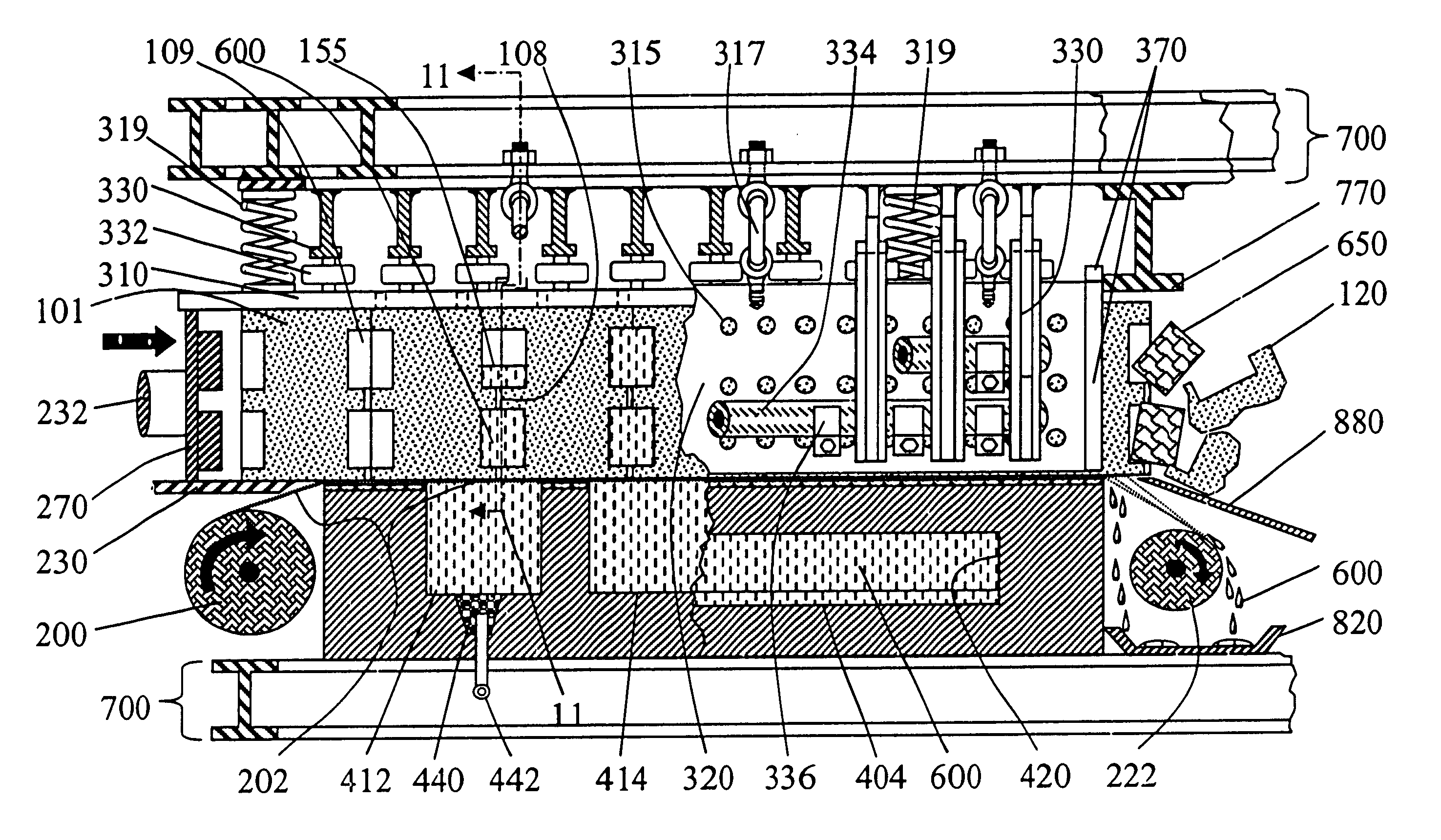
Reference is now made to the attached drawings that discloses descriptions of several of the embodiments for producing high integrity castings or moldings at high speed and yield with substantially decreased costs.

The preferred embodiment of the invention depends upon the material to be cast, the size of the operation, and the primary molding method.

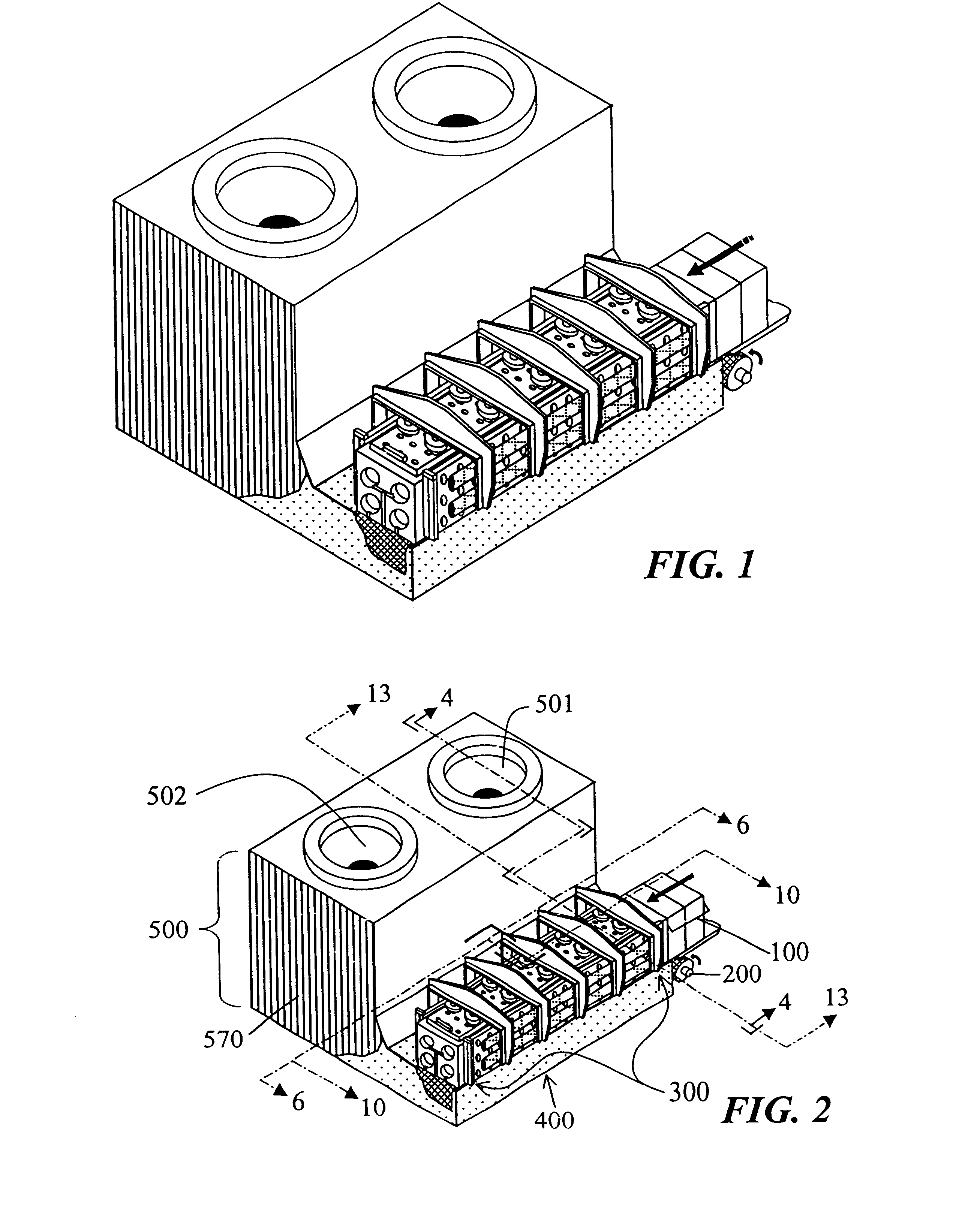
In FIG. 1 the machine is in a simplified form. The length and number of individual components has been reduced. In FIG. 2, major assembled components of the preferred embodiment are:

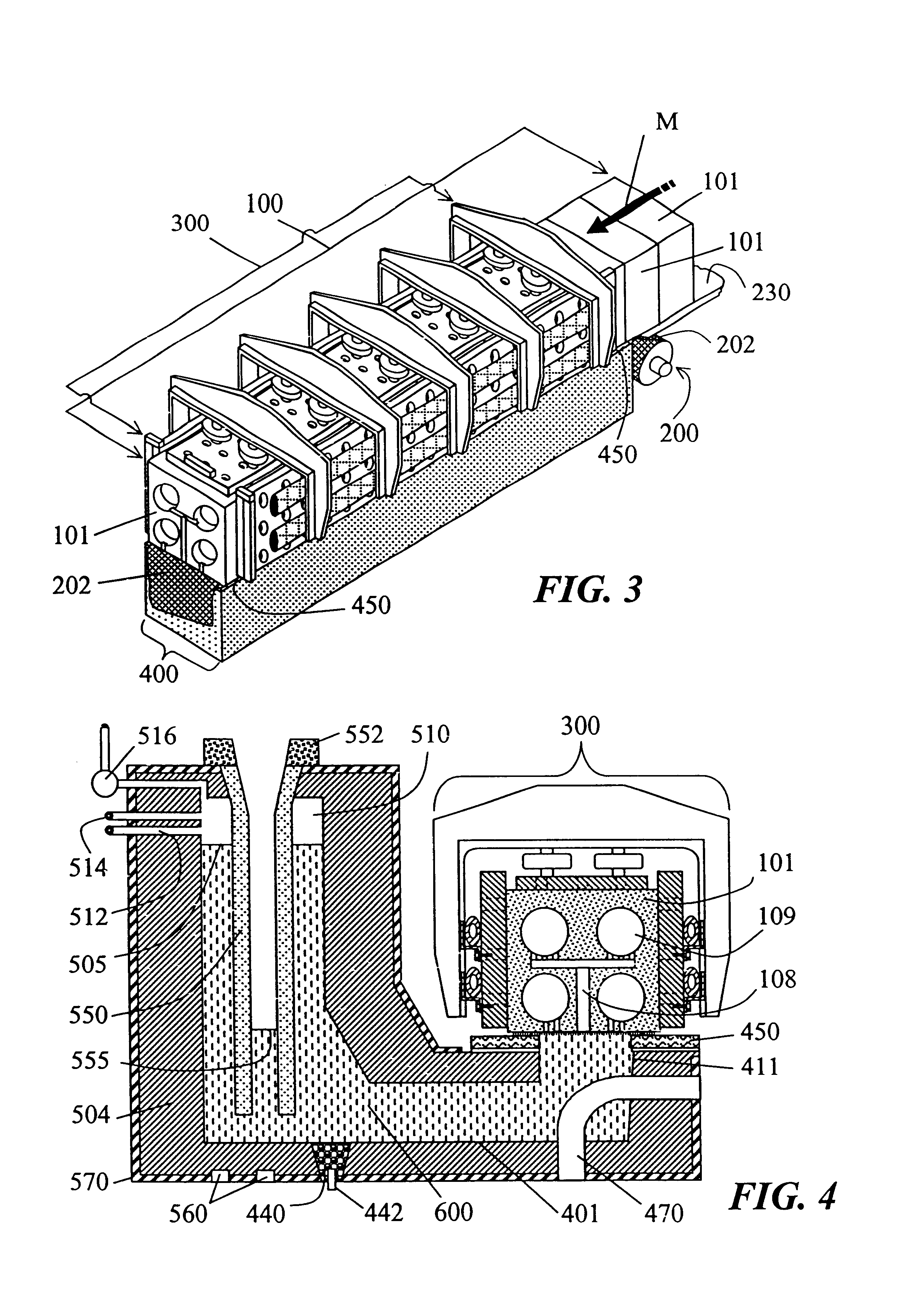
a line of molds 100;

a filter cloth dispensing roll 200;

a mold support / pressure restraint device 300;

a single or multi-chamber, filling and feeding device 400;

a single or multi-chamber holding furnace or vessel 500, utilizing vacuum and / or pressure, controlled by a computer (not shown) processing a control algorithm according to input data;

a stitching device for alloy modification of molten metal 600;

an operating casting facility, or superstructure 700, with a...


PUM

PropertyMeasurementUnit
shrinkage propertiesaaaaaaaaaa
pressureaaaaaaaaaa
timeaaaaaaaaaa

Abstract

Mold filling and feeding device (400) and process including using refractory filter cloth (202) to seal a mold line (100), in continuous conveyance, to a multi-stage pressurized filling and feeding device. The mold line (100) consists of vertically parted or horizontally parted green sand molds (101), or an extruded bed of media carrying various types of molds, including green sand, nobake, lost foam, investment casting shells, etc. These molds are bottom or side filled while moving for increased production rates. Feeding under pressure, while moving, is a second operation that improves casting integrity. The process includes a new and more efficient method of treating iron with magnesium for compacted graphite or ductile iron. A stitch (242) of filter cloth (202) holds modifying alloy (630) to the molds (101). A vacuum and pressure controlled column (550) provides consistent flow to thin walled castings, and pressurized feeding for heavy castings. Radiant energy losses are contained in the automatic system. The process and several special purpose machine components make a unified system for hardening liquid (600) such as molten metal in casting of aluminum alloy wheels or other metal castings, and also plastic polymer, rubber tires, etc., or food stuff, as in molded chocolate candy.

Description

TECHNICAL FIELD OF INVENTIONThis invention relates to the apparatus and processes of molding and casting, particularly to molten metal casting, for such as aluminum alloy wheels, but also to other thermally or chemically hardening liquids such as solidified foodstuff, plastics, rubber or other polymers formed in molds into solid articles for such as the automotive, aerospace industries, and food technology.BACKGROUND AND PRIOR ARTFor centuries, molds have been filled with molten metal to solidify into desired shapes. The processes have been adapted to other natural and synthetic hardening fluids ranging from chocolate to plastics, for example. The fluid or liquid may be poured under gravity from a vessel into an opening in the top of the mold. It may be pumped or flow under pressure into any area of the mold. The mold generally consists of a top and bottom section joined along a somewhat horizontal parting line. A cavity within the assembled mold corresponds to the desired solid sha...

Claims


Application Information

Patent Timeline
Patent Type & Authority Patents(United States)
IPC IPC(8): A23P1/10A23G3/34A23G1/20A23G1/04A23G3/02B22D18/04B22D2/00B22D33/00B22D43/00B29C39/40B29C39/24B29C39/22B29C39/04B29C39/06B29C31/04A23L1/00
CPCA23G1/206A23G3/0027A23G3/0257A23L1/0073A23P1/105B22D2/003B29C39/405B22D33/005B22D43/004B29C39/06B29C39/24B22D18/04B29C31/04A23P30/10
Inventor HERRON, DAVID J.
Owner HERRON DAVID J
Why Eureka
Try Eureka