Camber control suspension

a technology of suspension and camber, applied in the direction of suspension arms, resilient suspensions, vehicle components, etc., can solve the problems of deteriorating contact capability of tire treads, affecting the stability of straight running vehicles, and not always constant camber,

Inactive Publication Date: 2003-10-28
HYUNDAI MOTOR CO LTD
View PDF6 Cites 25 Cited by
  • Summary
  • Abstract
  • Description
  • Claims
  • Application Information

AI Technical Summary

Problems solved by technology

However, camber is not always constant while the vehicle is running, but changes in angle according to the running state of the vehicle, mainly depending on types of selected suspensions.
However, there will be a great change in the camber angle as the vehicle rolls as shown in FIG. 2, thereby deteriorating contact capability of a tire tread which w

Method used


Image

  • Camber control suspension
  • Camber control suspension
  • Camber control suspension

Examples


Embodiment Construction

Hereinafter, a preferred embodiment of the present invention is described in detail with reference to accompanying drawings in which like parts are identified identically.

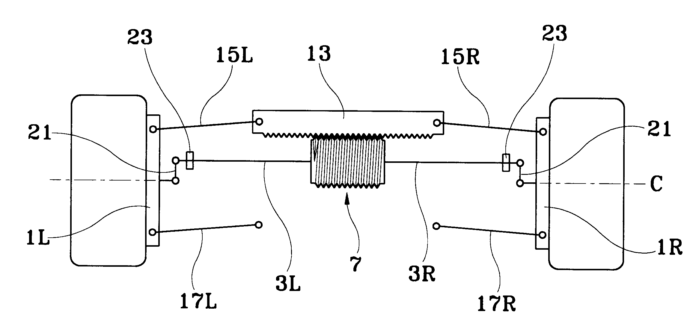
FIGS. 5 and 6 illustrate a camber control suspension in accordance with an embodiment of the present invention, comprising: two roll detecting links 3L, 3R respectively connected to the front part of a wheel rotational center at a knuckle 1L of a left wheel and to the rear part of the wheel rotational center at a knuckle 1R of the right wheel and forming a L shape by being bent at a position where the links cross with a vertical line passing through the wheel rotational center C; a differential gear unit 7 having bevel gears installed at each end of the two roll detecting links for both side gears 5L, 5R; a worm gear 11 formed at a differential gear case 9 of the differential gear unit 7; a camber control rack 13 formed with a gear meshed to the worm gear 11 and horizontally installed with a vehicle axle to make a ...


PUM


Abstract

The invention relates to a camber control suspension of a vehicle that can form a stable camber angle even at the time when the vehicle rolls as well as when bumping and rebounding, including a camber control rack and camber control links which function to control camber of wheels by stopping or moving according to the vertical motion of both wheels. As a result, a most stable ground contact state of the tires at all times is achieved to sufficiently enhance the groiund contact force of the tires at any running state of the vehicle.

Description

1. Field of the InventionThe present invention relates to a suspension of a vehicle, and more particularly to a suspension of a vehicle that can form a stable camber angle even at the time when the vehicle bumps and rebounds as well as when it rolls.2. Brief Description of the Prior ArtIn general, a camber is an angle that forms between a center line of wheels and a vertical line about road surface. The camber prevents the bottom part of front wheels from being stretched by weight and also the wheels from being loosened while a vehicle is running. Especially, camber also plays a role in facilitating an easy manipulation of a steering wheel along with an inclination angle of a kingpin.However, camber is not always constant while the vehicle is running, but changes in angle according to the running state of the vehicle, mainly depending on types of selected suspensions. The different types of changes are described in accordance with a few types of suspensions.First of all, FIG. 1 illu...

Claims


Application Information

Patent Timeline
IPC IPC(8): B60G3/26B60G3/18B60G3/00
CPCB60G3/26B60G2800/012B60G2204/419B60G2200/46B60G3/00
Inventor WOO, SEUNG-HOON
Owner HYUNDAI MOTOR CO LTD
Why Eureka
Try Eureka