Automated spray form cell

a technology of spray form and automatic spraying, which is applied in the direction of coating, manufacturing tools,foundry moulding apparatus, etc., can solve the problems of uncontrolled spray process, significant undesirable effects in finished products, and deflection of finished products in uncontrolled spray processes, so as to minimize or eliminate stress-inducing characteristics, accurate surface temperature distribution measurements, and high sensitivity

Inactive Publication Date: 2003-11-04
FORD MOTOR CO
View PDF13 Cites 24 Cited by
  • Summary
  • Abstract
  • Description
  • Claims
  • Application Information

AI Technical Summary

Benefits of technology

According to the present invention, a two-wavelength imaging pyrometer is utilized to provide real-time measurement of the surface temperature distribution of a spray formed article. The imaging pyrometer provides a continuous stream of high resolution (on the order of 32,000-pixels) thermal images of the steel billet throughout the spray-forming process. The preferred imaging pyrometer, with its high sensitivity, measures temperatures as low as 392.degree. Fahrenheit (200.degree. Celsius). Through the use of two-wavelength sensing, the pyrometer is capable of making accurate surface temperature distribution measurements despite the scattering of light due to the dusty environment in the spray-forming process. Similarly, the selected pyrometer is also capable of making accurate temperature distribution measurements in spite of other opacity issues such as when the optical windows of the device become coated with dust and the degree at which light passes therethrough significantly degrades.
From an operational standpoint, the incorporation of such a real-time temperature measuring device enables control strategies that minimize or eliminate the stress-inducing characteristics of previously known processes. For instance, with an accurate, real-time, two-dimensional, temperature map of the exposed surface of the article being formed, spray gun operation and movement patterns can be altered to, among other things, minimize temperature variations across the article. From a monitoring or feed back perspective, the real-time temperature monitoring enabled by the pyrometer makes it possible to evaluate changes affected at the gun, regarding their effect on the article being sprayed.
FIG. 10 is a perspective view an example of a light shielding receptacle in the form of a cylindrical or bucket-styled enclosure that may be provided in the spray-form cell for temporarily concealing the high intensity light produced by the operating plasma torches thereby enhancing accuracy of the pyrometer's readings;

Problems solved by technology

These variations or temperature gradients that are experienced across the body of the article during the spray-forming process can produce significant undesirable effects in the finished product.
One of the more significant detrimental effects that may occur is typically manifest as internal stress that is trapped within the substantially rigid article after its manufacture.
Even though minor latent stresses may not significantly affect a finished article, it is not uncommon for stresses of magnitudes high enough to warp or otherwise cause deformation and deflection in the finished article to occur in uncontrolled spray processes.
Still further, even minor deflections due to internalized stress can render conventional spray form processes unuseable when precision tooling is required for particular finished products or articles.
Additionally, an increased magnitude in the experienced temperature gradients will result due to the greater time required to complete these larger bodies.
The result can be undesirable migrating "hot spots" or trails across the finished product.
But, in spite of the recognized need, a continuing failure in the art has been an inability to accurately monitor and measure the experienced temperature(s) across the article's surface during the spray forming process on a real-time basis.
Consequently, there has been a continuing inability to affect proper control over at least the heat energy input to the metal on a similar real-time basis for obviating the problems associated with temperature gradients induced in the article being spray formed.

Method used


Image

  • Automated spray form cell
  • Automated spray form cell
  • Automated spray form cell

Examples


Embodiment Construction

As required, detailed embodiments of the present invention are disclosed herein;

however, it is to be understood that the disclosed embodiments are merely exemplary of the invention that may be embodied in various and alternative forms. The figures are not necessarily to scale, some features may be exaggerated or minimized to show details of particular components. Therefore, specific structural and functional details disclosed herein are not to be interpreted as limiting, but merely as a basis for the claims and as a representative basis for teaching one skilled in the art to variously employ the present invention.

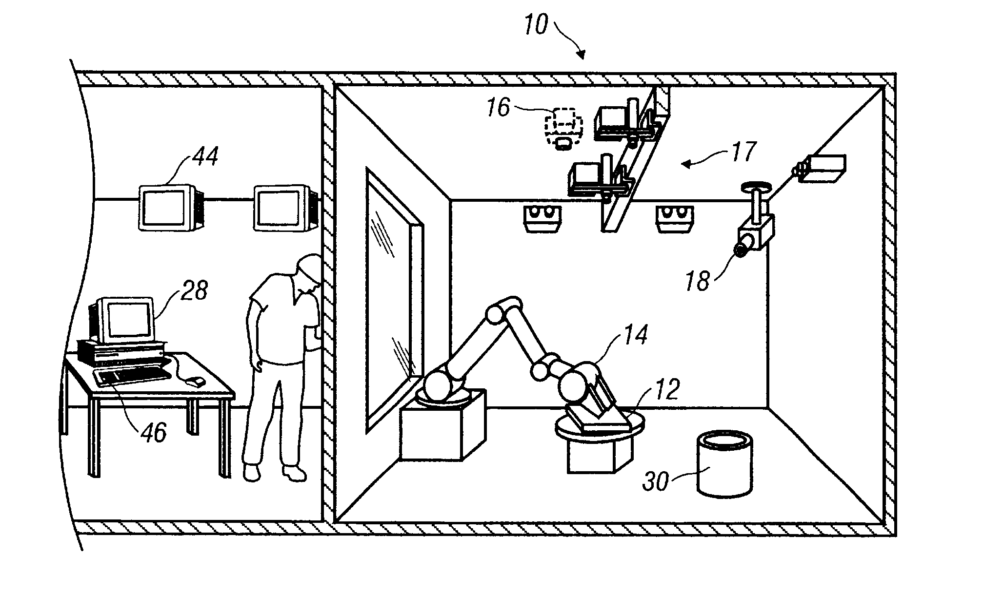
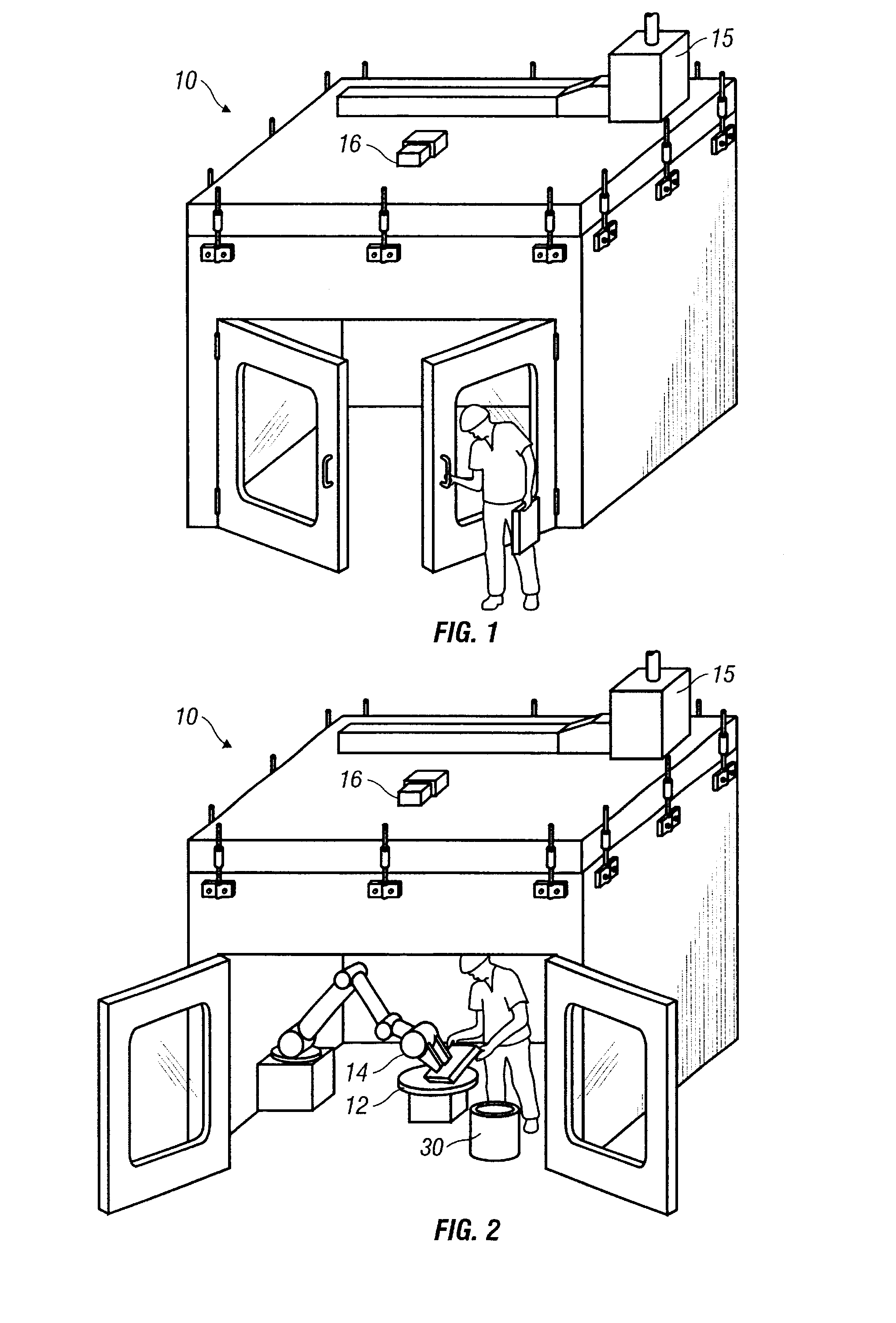
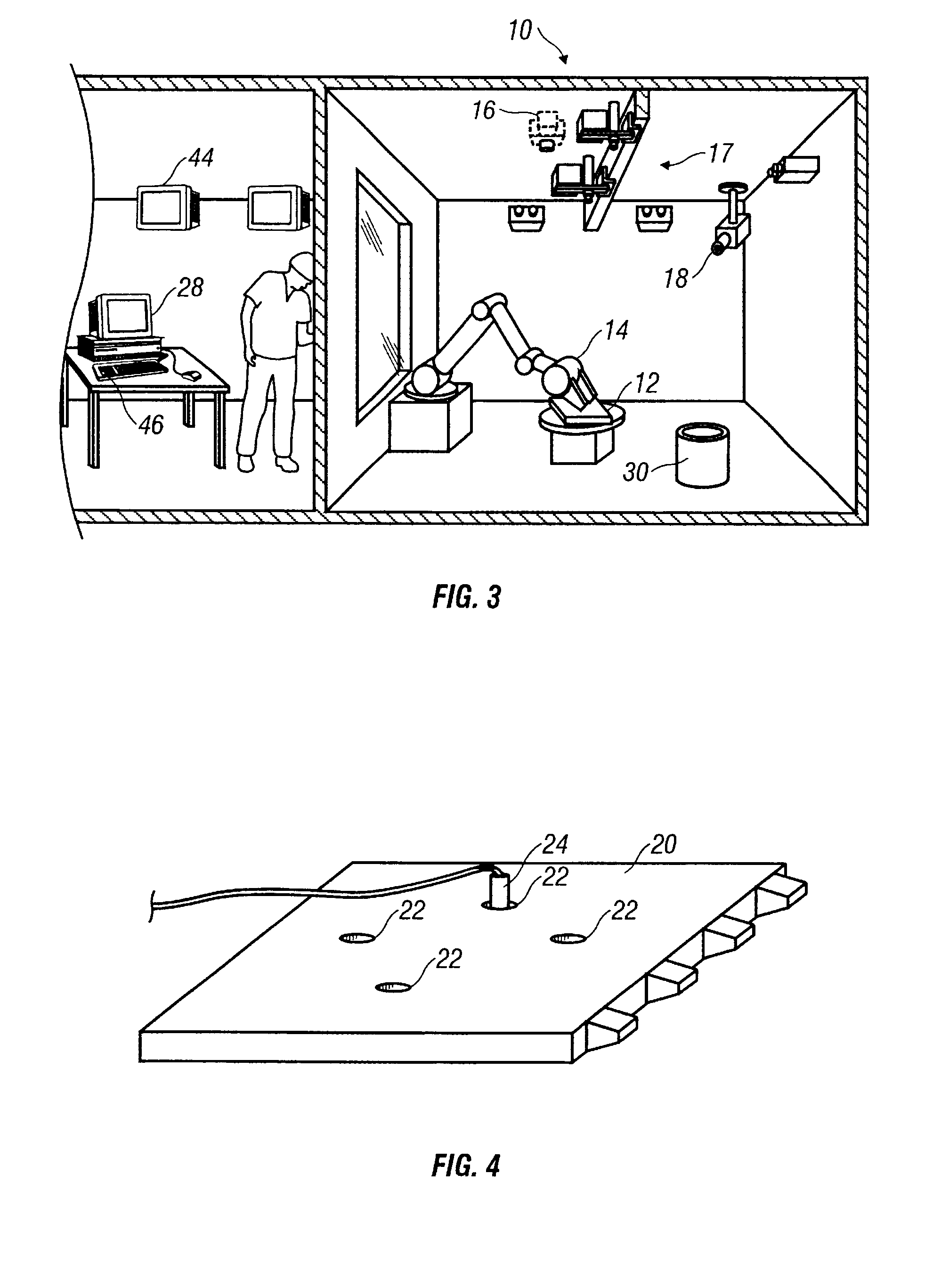
As will be described herein and which is illustrated in the accompanying drawings, exemplary trials utilizing the arrangement(s) and method(s) of the present invention have been undertaken. In these trials, an imaging pyrometer was installed in a rapid tooling spray forming facility, a structure that is also commonly referred to as a spray-form cell. An exemplary cell is il...


PUM

PropertyMeasurementUnit
wavelengthaaaaaaaaaa

Abstract

Spray form cell including a two-wavelength imaging pyrometer adapted to provide real-time measurement of the surface temperature distribution of a metal billet thereby formed. The steel billets may be advantageously used as tools in metal forming processes, injection molding, die casting tooling and other processes that require hard tooling, such as in the automotive industry. The steel billet is formed based on a goal of uniform surface temperature distribution thereby minimizing thermal stresses induced within the steel article thereby produced.

Description

BACKGROUND OF INVENTION1. Technical FieldThe present invention relates generally to spray forming methods and arrangements, and more specifically to spray form cell design which includes automated features for monitoring and controlling performance aspects of a spray form process.2. Background ArtIt is a known process to spray-form certain articles using moltenizing arc guns with metal wire supplied thereto. In order to moltenize the wire and form sprayable metal droplets, a significant amount of energy, typically manifest as heat, is applied at the arc gun to the wire. As a result, the temperature of the droplets is significantly elevated, and this elevated temperature is at least partially carried onward to the article being spray formed. Once the droplets land on the article and become a constituent component thereof, a portion of the heat energy travels conductively into the article, while the balance of the heat energy dissipates to the surrounding atmosphere. As a result, the ...

Claims


Application Information

Patent Timeline
Patent Type & Authority Patents(United States)
IPC IPC(8): B22D23/00C23C4/18C23C4/12C23C4/02
CPCB22D23/003C23C4/02C23C4/185C23C4/18C23C4/12B22D17/32
Inventor ALLOR, RICHARD LCOLLINS, DAVID ROBERTNICHOLSON, JOHN MICHAELGRINBERG, GRIGORIY
Owner FORD MOTOR CO
Why Eureka
Try Eureka