Power transmission mechanism

a technology of transmission mechanism and drive wheel, which is applied in the direction of gearing, mechanical control devices, instruments, etc., can solve the problems of increasing the manufacturing cost of the vehicle, difficult to secure a space for installing the mechanism in the vehicle, and the torque required to drive the drive wheels is relatively larg

Inactive Publication Date: 2003-11-04
HONDA MOTOR CO LTD
View PDF10 Cites 26 Cited by
  • Summary
  • Abstract
  • Description
  • Claims
  • Application Information

AI Technical Summary

Benefits of technology

According to this power transmission mechanism, the plurality of change gears selectively mesh with each other, whereby the driving force from the engine is transmitted to the drive wheels according to a transmission gear ratio between the meshed change gears, whereby the hybrid vehicle is driven for traveling. Further, when the connection mode of the electric motor is switched to the output shaft connection mode by the switching mechanism, the electric motor is connected to the output shaft via the first gear and the output shaft gear meshing with each other, and thereby connected to the drive wheels. As a result, the electric motor can be used as a drive source for driving the drive wheels, and even if the power transmission mechanism undergoes a shifting operation during running of the vehicle, the drive wheels can be driven by the electric motor, whereby it becomes possible to prevent occurrence of an idle running feeling. Further, when the connection mode is switched to the input shaft connection mode by the switching mechanism, the electric motor is connected to the input shaft via the second gear and the input shaft gear meshing with each other, and thereby connected to the engine. Consequently, when the output shaft and the input shaft are disconnected from each other during stoppage of the engine, it is possible to crank the engine by the electric motor. This enables the electric motor to be used as a starter motor. As described above, one electric motor can be employed as the drive source for driving drive wheels and as the drive source for cranking the engine, which not only makes it possible to reduce manufacturing costs of the vehicle but also makes it easy to secure a space for mounting the transmission mechanism in a hybrid vehicle. Further, since the electric motor has the first gear or the second gear meshing with the gear of the transmission, by exploiting gear ratios between these gears, the drive wheels can be driven with a torque smaller than that of the conventional electric motor which is directly connected to the output shaft of the transmission. This makes it possible to design the electric motor compact in size, thereby making it easy to secure a mounting space of the transmission mechanism in the vehicle.
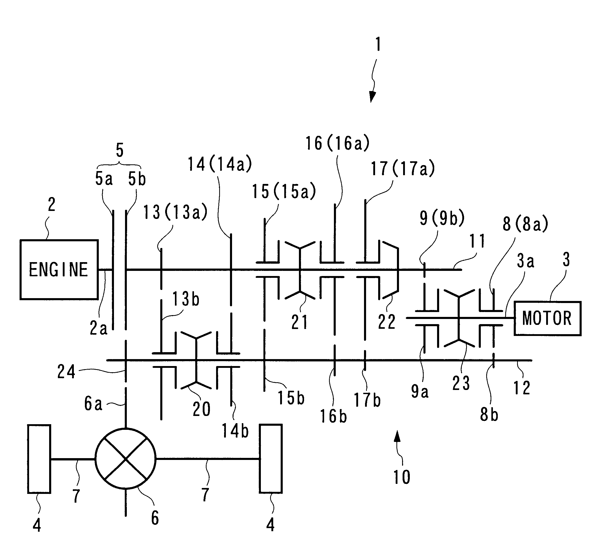
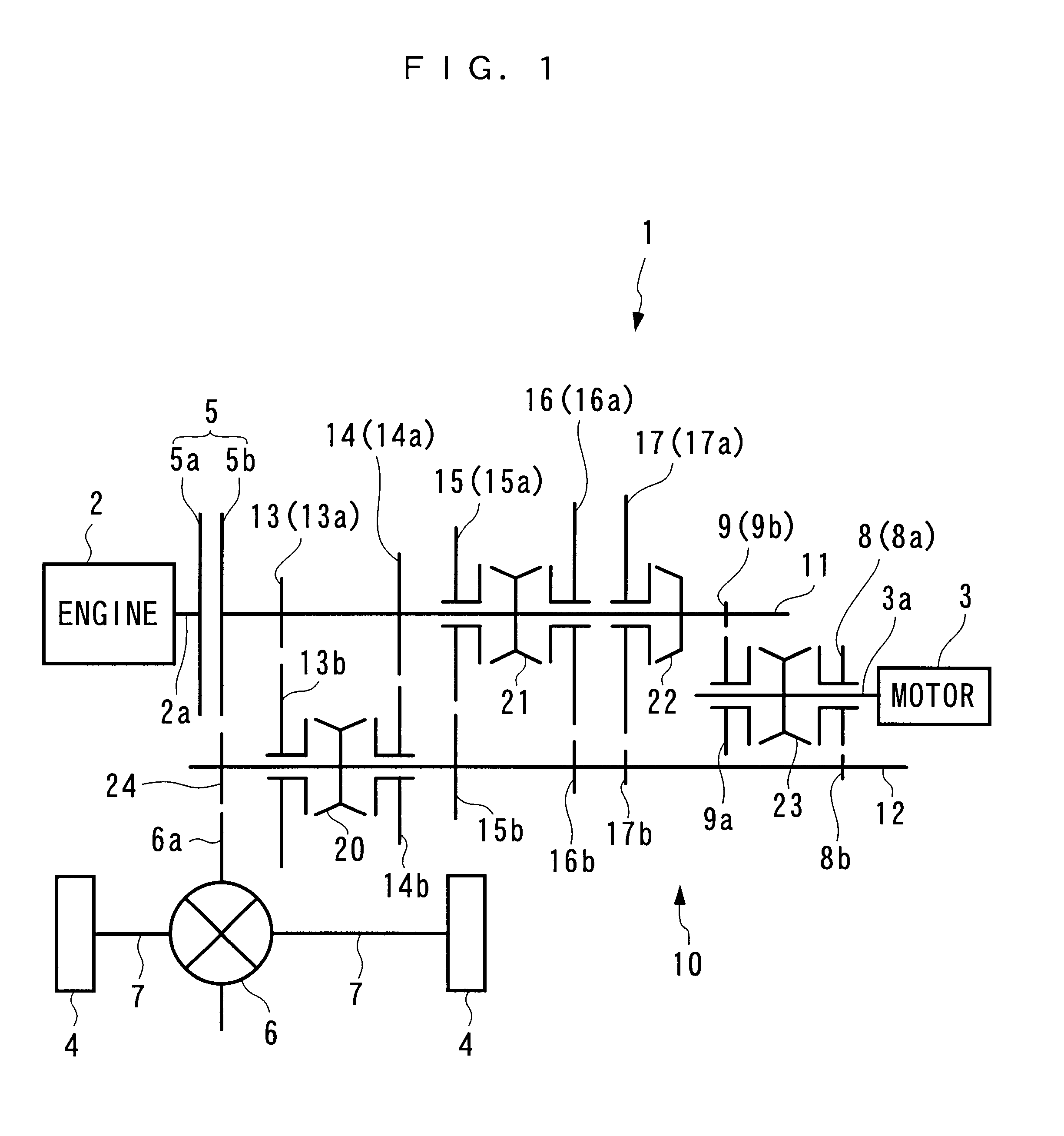
According to this preferred embodiment, when the connection mode is switched to the output shaft connection mode by the switching mechanism, the first gear meshes with the output shaft gear via the input shaft idle gear, whereby the drive wheels are driven by the electric motor. Further, in the input shaft connection mode, the second gear meshes with the input shaft integrated gear, whereby the engine is cranked by the electric motor. In this case, generally, the transmission includes idle gears rotatable about the input shaft and the output shaft, and integrated gears as change gears, and hence if such existing change gears are employed as input shaft idle gears, input shaft integrated gears, and output shaft gears, the above effects can be obtained without adding extra gears other than the change gears. Further, since the electric motor and the drive shaft thereof can be arranged in parallel with the gear shafts of the transmission, lengths in the axial direction, such as the lengths of the input shaft and so forth, can be reduced as a whole, thereby ensuring excellent mounting performance of the hybrid vehicle.
According to this preferred embodiment, in the output shaft connection mode, the first gear meshes with the output shaft integrated gear, whereby the drive wheels are driven by the electric motor. Further, in the input shaft connection mode, the second gear meshes with the input shaft gear via the output shaft idle gear, whereby the engine is cranked by the electric motor. Further, for the same reason as described hereinabove, the above advantageous effects can be obtained without adding extra gears, and lengths in the axial direction, such as the lengths of the input shaft and so forth, can be reduced as a whole, thereby ensuring excellent mounting performance of the hybrid vehicle.
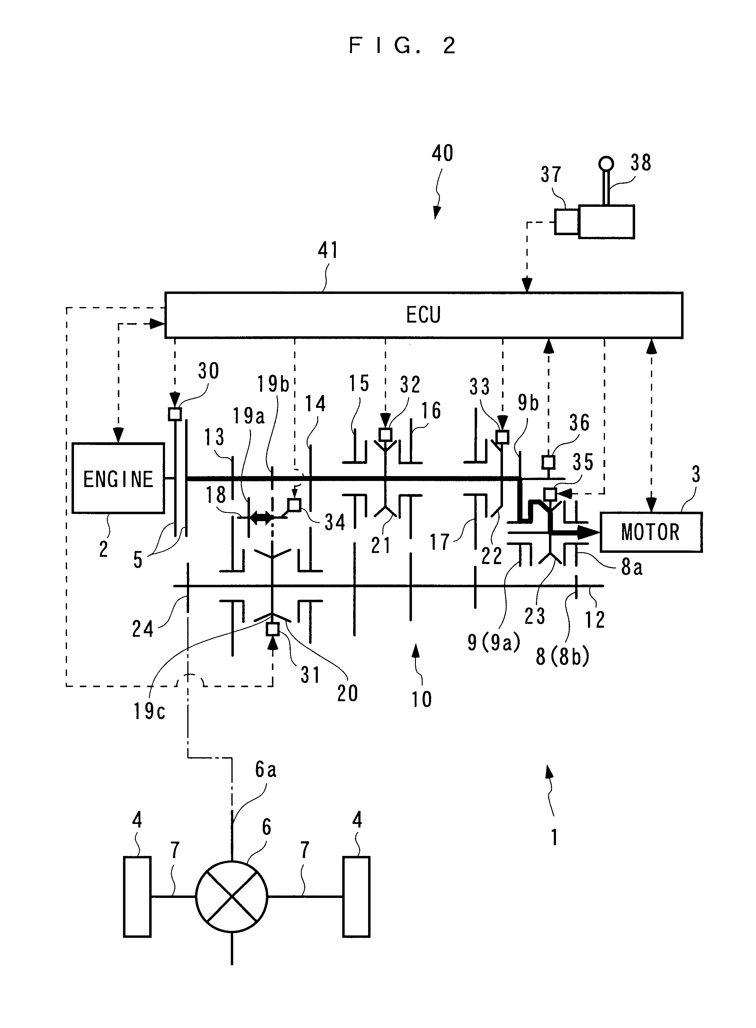
According to this preferred embodiment, when the connection mode is switched to the cut-off mode, the electric motor is disconnected from the output shaft and the input shaft, so that it is possible to prevent the electric motor from offering an extra rotational resistance when the drive wheels are being driven by the engine, thereby making it possible to enhance fuel economy.
According to this preferred embodiment, when the reverse gear simultaneously meshes with one of the change gears of the input shaft and one of the change gears of the output shaft, the switching mechanism switches the connection mode to the input shaft connection mode in a state in which the transmission and the engine are disconnected from each other by the clutch, whereby the electric motor and the input shaft are connected to each other. Therefore, the electric motor offers a rotational resistance to the input shaft to thereby reduce the rotation of the input shaft, and hence when the reverse gear is caused to simultaneously mesh with the one of the change gears of the input shaft and the one of the change gears of the output shaft so as to change the traveling mode of the vehicle from a forward one to a backward one, the rotation of the input shaft is reduced by inertia of energy, and the reverse gear in a stopped state is caused to mesh with the one of the change gears of the input shaft whose rotation is reduced. This makes it possible to prevent occurrence of a gear squeal. In this case, if the regeneration operation by the electric motor is additionally carried out, the rotation of the engine can be reduced in a shorter time period, whereby it is possible to prevent occurrence of a gear squeal, and recover regenerative electric power at the same time.

Problems solved by technology

In addition thereto, if a starter motor for starting the engine is separately provided, still another electric motor is necessitated, which leads to increased manufacturing costs of the vehicle and makes it difficult to secure a space for installing the mechanism in the vehicle.
Further, since the motor for driving the drive wheels has a drive shaft thereof directly connected to the output shaft of the transmission, a relatively large torque is required to drive the drive wheels.
This necessarily leads to an increased size of the motor, resulting in further increased manufacturing cost of the mechanism.
This results in degraded fuel economy.

Method used


Image

  • Power transmission mechanism
  • Power transmission mechanism
  • Power transmission mechanism

Examples


Embodiment Construction

The invention will now be described in detail with reference to the drawings showing a power transmission mechanism according to an embodiment thereof. FIG. 1 schematically shows the arrangement of a hybrid vehicle to which is applied the power transmission mechanism according to the present embodiment. FIG. 2 schematically shows the arrangement of a control system for controlling the power transmission mechanism, with devices and parts added to the FIG. 1 power transmission mechanism. The power transmission mechanism 1 is capable of selectively connecting an engine 2 and an electric motor (hereinafter referred to as the "motor") 3, both of which are mounted in a hybrid vehicle, not shown, to drive wheels 4, 4, and includes a clutch 5, a transmission 10, a differential 6, drive shafts 7, 7, etc. The engine 2 is mechanically connected to the drive wheels 4, 4 via the clutch 5, the transmission 10, the differential 6, and the drive shafts 7, 7. The motor 3 is mechanically connected to...


PUM


Abstract

A power transmission mechanism which is capable of employing one electric motor as a drive source for driving drive wheels and as a drive source for cranking an engine, thereby making it possible to reduce manufacturing costs of the hybrid vehicle, and preventing the motor from offering an extra rotational resistance to the engine when the drive wheels are being driven by the engine, thereby making it possible to enhance fuel economy. In the power transmission mechanism for transmitting the driving force from the engine and / or the electric motor to the drive wheels, when a synchro-clutch for the electric motor, driven by a switching actuator, connects the drive shaft of the electric motor and a driving drive shaft gear to each other, the electric motor is connected to the drive wheels via a meshing gear pair (driving drive shaft gear and driving output shaft gear), whereas when the synchro-clutch connects the drive shaft of the electric motor and a cranking drive shaft gear to each other, the electric motor is connected to the engine via a meshing gear pair (cranking drive shaft gear and cranking input shaft gear), the input shaft of the transmission, and a clutch.

Description

1. Field of the InventionThis invention relates to a power transmission mechanism for transmitting a driving force from at least one of an engine and an electric motor to drive wheels.2. Description of the Prior ArtConventionally, a power transmission mechanism of this kind has been proposed e.g. by Japanese Laid-Open Patent Publication (Kokai) No. 11-69509, which includes a multi-stage transmission for connecting an engine to a differential gear, and a clutch for connecting and disconnecting the multi-stage transmission to and from the engine. The multi-stage transmission has an output shaft directly connected to the drive shaft of a motor for driving drive wheels. When the power transmission mechanism performs a shifting operation during running of the vehicle being driven by the engine, the motor drives the output shaft of the multi-stage transmission immediately after disengagement of the clutch, thereby preventing occurrence of a sense of loss of a driving force during running ...

Claims


Application Information

Patent Timeline
Patent Type & Authority Patents(United States)
IPC IPC(8): B60K6/00B60K6/04F16H3/089F16H3/08B60K6/20B60K17/04B60K6/24B60K6/26B60K6/36B60K6/387B60K6/40B60K6/48B60K6/547B60K17/02B60L50/16B60W10/08B60W20/00
CPCB60K6/48B60W10/08B60W10/10F16H3/089B60K6/547Y10T74/20018B60W20/00Y02T10/6221Y10S903/903Y10S903/951Y10S903/905Y10S903/945Y10S903/909Y10S903/906Y10S903/914Y10S903/919Y02T10/62B60K2006/268B60K6/36
Inventor MARUYAMA, TAIJI
Owner HONDA MOTOR CO LTD
Why Eureka
Try Eureka