Linac focused by graded gradient

Inactive Publication Date: 2003-11-04
JEFFERSON SCI ASSOCS LLC
View PDF2 Cites 3 Cited by
  • Summary
  • Abstract
  • Description
  • Claims
  • Application Information

AI Technical Summary

Benefits of technology

The present invention provides an improvement in the beam dynamic control, beam confinement, beam stability, and an increased allowable d

Problems solved by technology

Other design limitations include losses from beam mismatch, and excessive gaps between the drift tubes, which can cause particle dispersion.
One of the most troublesome problems to address in t

Method used


Image

  • Linac focused by graded gradient
  • Linac focused by graded gradient
  • Linac focused by graded gradient

Examples


example 1b (

Prior Art)

Split Linac, Constant Gradient Focusing

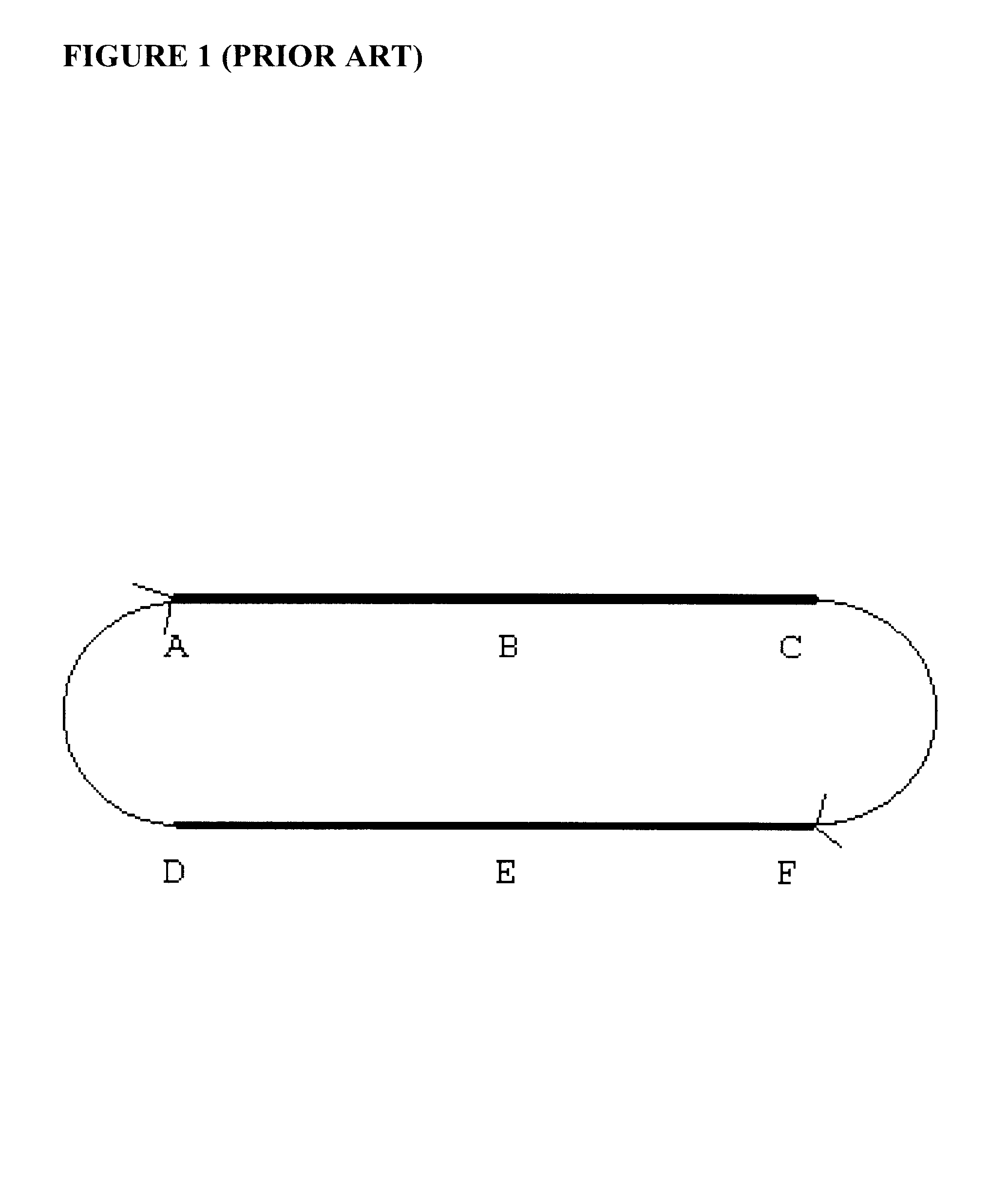
In FIG. 1, for this example, points A, B, and C define one linac, and points D, E, and F define a second linac, a "split" linac structure. The focussing profile at point s A, B, C, D, E, and F s as follows (in tabular form for ease of reference hereinafter):

A f=f(E.sub.inject)

B f=f(E.sub.inject)

C f=f(E.sub.inject)

D f=f(E.sub.inject)

E f=f(E.sub.inject)

F f=f(E.sub.inject)

As one of skill in the art knows, a constant gradient is applied at each point of the pair of linacs to create the same field strength for purposes of focusing. However, the energy levels of the accelerated particles at each of the points is as follows: ##EQU1##

Thus, it may be clearly seen that for a constant gradient focusing scheme, in either a single or split linac, frequent mismatches between the particle beam energy and the focusing field strength are observed.

Turning now to the constant focal length focussing scenario, we can see that a similar mismatch is observe...

example 1c (

Prior Art)

Single Linac, Constant Focal Length Focusing

For this example, the focusing profile along the beam path is set to a constant focal length. As for the constant gradient, despite the fact that the focussing strength alters along the beam path, it is also mismatched to the energy level of the particle beam.

For Example 1C (Prior Art), the focusing profile of FIG. 1 is as follows:

A f=f(E.sub.inject)

B f=f(E.sub.mid), where E.sub.mid =E.sub.inject +(E.sub.inject -E.sub.final) / 2

C f=f(E.sub.final)

Points D, E, and F are inactive, as this example is a single linac.

The corresponding beam energy levels are as follows: ##EQU2##

Thus, the beam mismatch problem exists in a single linac with constant focal length focusing. The following example illustrates the problem continues even when a split linac is utilized.

example 1d (

Prior Art)

Split Linac, Constant Focal Length Focusing

For Example 1D (Prior Art), the focusing profile of FIG. 1 is as follows:

A f=f(E.sub.inject)

C f=f(E.sub.mid) where E.sub.mid =E.sub.inject +(E.sub.inject -E.sub.final) / 2

F f=f(E.sub.mid) where E.sub.mid =E.sub.inject +(E.sub.inject -E.sub.final) / 2

D f=f(E.sub.final)

The corresponding beam energy levels are as follows: ##EQU3##

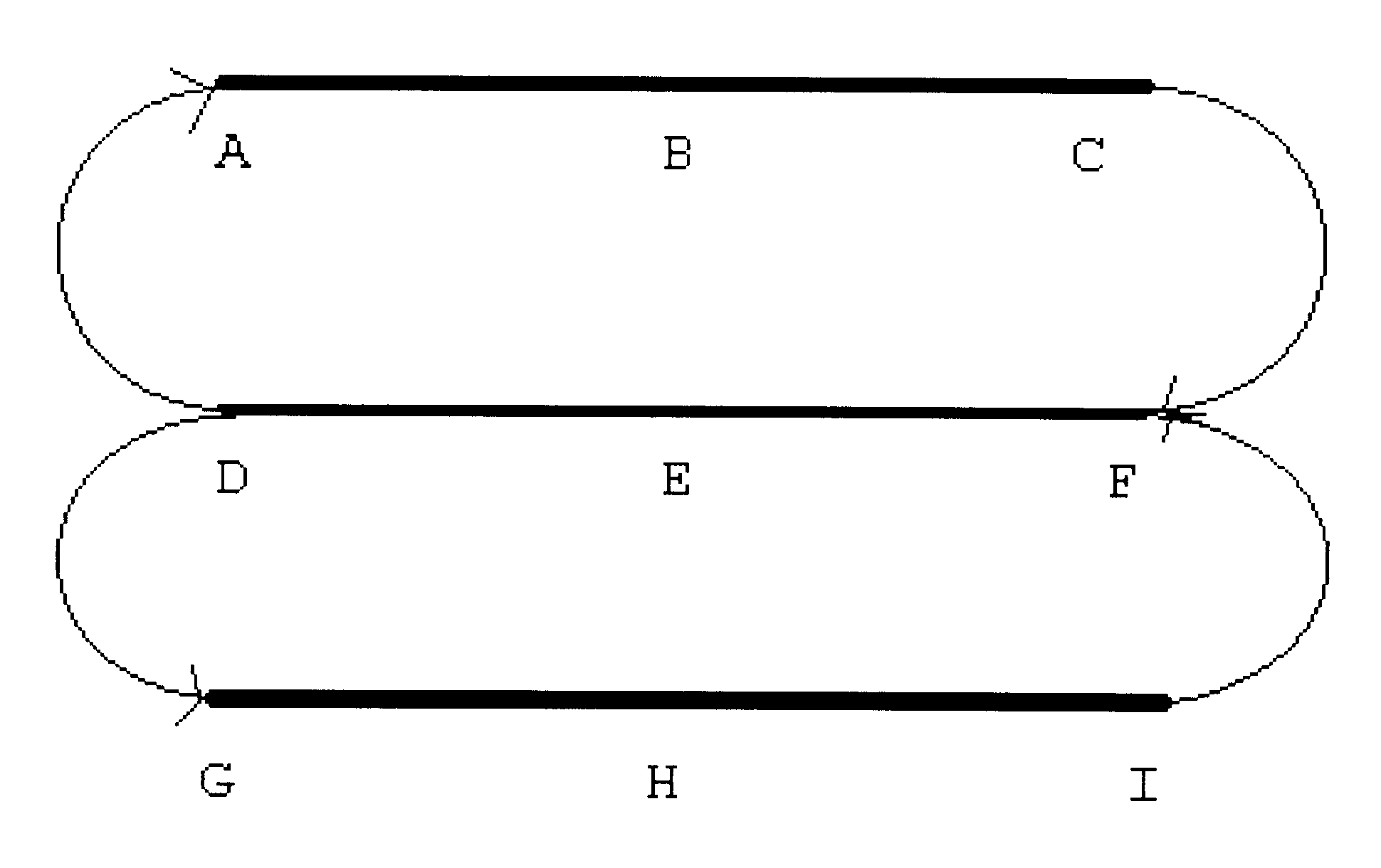
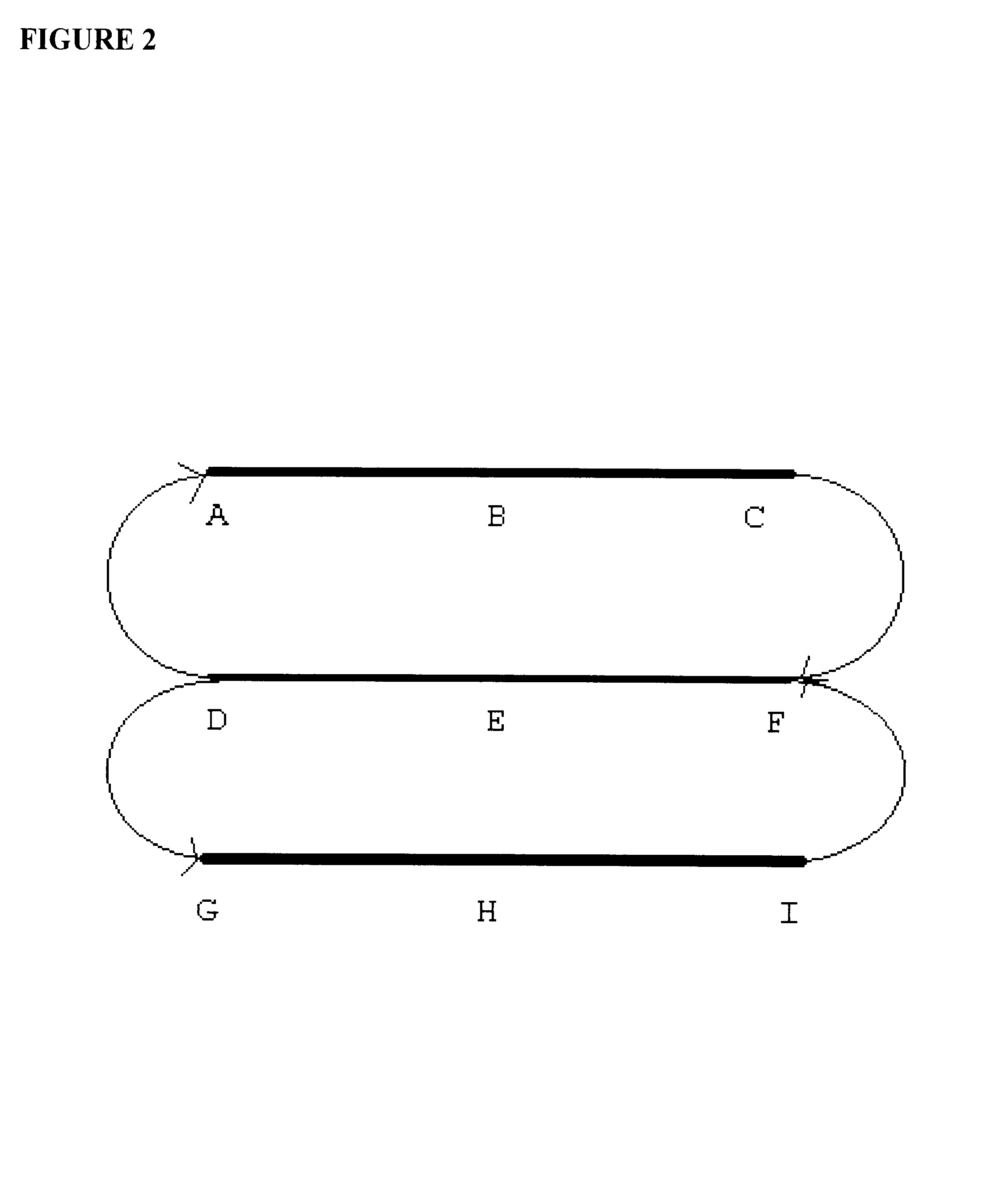
Turning now more precisely to the invention, the novel "graded gradient" beam focusing method of the present invention is clearly seen. The beam transport topology is shown in FIG. 2. It is noted that a split linac topology is illustrated in this example; however, one of skill in the art may easily apply this concept to multiple linac and / or multiple pass topology.

The focusing profile of the linac according to the present invention is as follows:

A f=f (E.sub.inject)

B f=f(E.sub.1 / 4), where E.sub.1 / 4 =E.sub.inject +(E.sub.final -E.sub.inject) / 4

C f=f(E.sub.inject)

F f=f(E.sub.1 / 2), where E.sub.1 / 2 =E.sub.inject +(E....


PUM


Abstract

A linear accelerator with improved efficiency is disclosed. The linear accelerator contains at least one lower beam energy recirculating linear accelerator which is focused along a constant focal length, and at least one higher beam energy recirculating linear accelerator which is focused along a constant focal length, and a full energy recirculating line which received the beam from the higher energy recirculating linear accelerator and reinjects it into the higher energy recirculating linear accelerator, thereby balancing the focusing profile to the beam energy. Better envelope control, focusing, and higher efficiency is observed in linacs according to the present invention.

Description

1. Field of the InventionThe present invention relates to the field of linear accelerators utilizing focusing fields. More specifically, it relates to multi-pass and energy-recovering linear accelerators and improved focusing methods therefor.2. Description of the Prior ArtLinear accelerators are generally well known in the prior art. Fundamentally, a linear accelerator works by utilizing radio-frequency (RF) energy to accelerate charged particles. The charged particles may be electrons, protons, ions, or any of various particles, which may be capable of holding a charge.RF energy is applied to the charged particles by at least one and usually a series of drift tubes, which vary in length and in other dimension and characteristics according to such design variables as the speed or size of the particle, the charge on the particle, the RF energy applied (wavelength and intensity), and focusing effects. As the drift tubes increase in number, a pronounced spreading effect is observed in...

Claims


Application Information

Patent Timeline
IPC IPC(8): H05H7/06H05H7/00H05H9/00
CPCH05H9/00H05H7/06
Inventor DOUGLAS, DAVID
Owner JEFFERSON SCI ASSOCS LLC
Why Eureka
Try Eureka