Beam shaping prior to harmonic generation for increased stability of laser beam shaping post harmonic generation with integrated automatic displacement and thermal beam drift compensation

a beam shaping and harmonic generation technology, applied in non-linear optics, instruments, lenses, etc., can solve problems such as “hot spots” or beam profile distortion, affecting reliable and controllable processes, and reducing the energy distribution profile of beams. , to achieve the effect of reducing the peak energy distribution profile of the beam and the generation of harmonic elements

Inactive Publication Date: 2009-01-29
HITACHI SEIKO LTD
View PDF3 Cites 30 Cited by
  • Summary
  • Abstract
  • Description
  • Claims
  • Application Information

AI Technical Summary

Benefits of technology

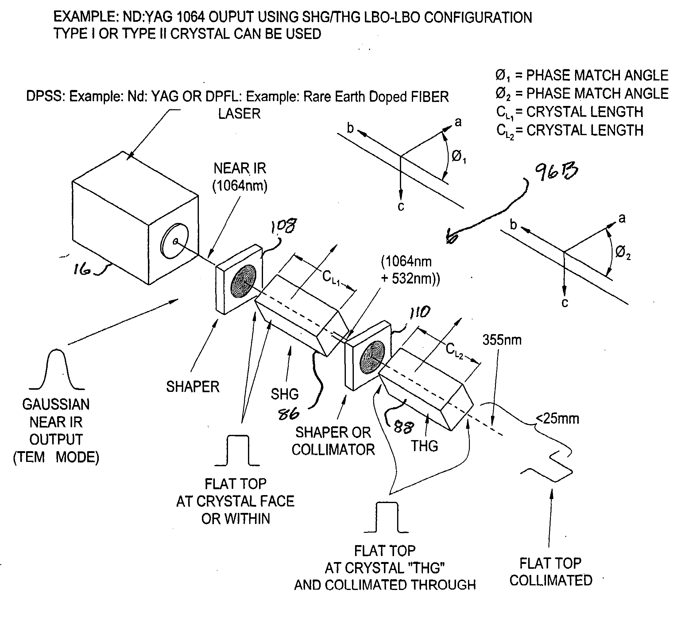
[0019]The present invention is directed to a harmonic generation / beam shaping system for use with a laser to generate a shaped beam having a wavelength having a harmonic relationship with a beam generated by the laser wherein the density of energy dissipation of the beam over the harmonic generation elements and the amplitudes of energy peaks in the energy distribution profile of the beam and thus within the harmonic generation elements are reduced. According to the present invention, the harmonic generation / beam shaping system includes a first harmonic generation element and a second harmonic generation element arranged sequentially along an axial beam path extending between an input from the laser and an output of the harmonic generation / beam shaping system and at least two beam shaping elements located along the axial beam path. At least one of the least two beam shaping elements is located between the second harmonic generation element and the laser to distribute the beam energy across a larger cross sectional area of at least one harmonic generation element or to reduce peaks in the energy distribution profile of the beam, or both.

Problems solved by technology

Such processes have become very complex, often involving the concurrent or sequential of use of single or multiple lasers or multiple types of lasers, such as visible, infra-red (IR) and ultraviolet (UV) lasers, in concurrent or sequential operations.
A number recurring problems of conventional laser systems of the prior art, however, directly affect the reliable and controllable “pointing” of a laser beam to a desired location.
Yet a third problem of the prior art is that of beam mode changes over time, which results in “hot spots”, or distortions of the beam profile.
If the profile of the beam is non-uniform or does not have an optimum Gaussian profile, the shape of the profile cannot be subsequently shaped into the preferred “flat top” profile, which will adversely effect the quality of the processes performed by the laser system, such as micro-machining or the drilling of microvias.
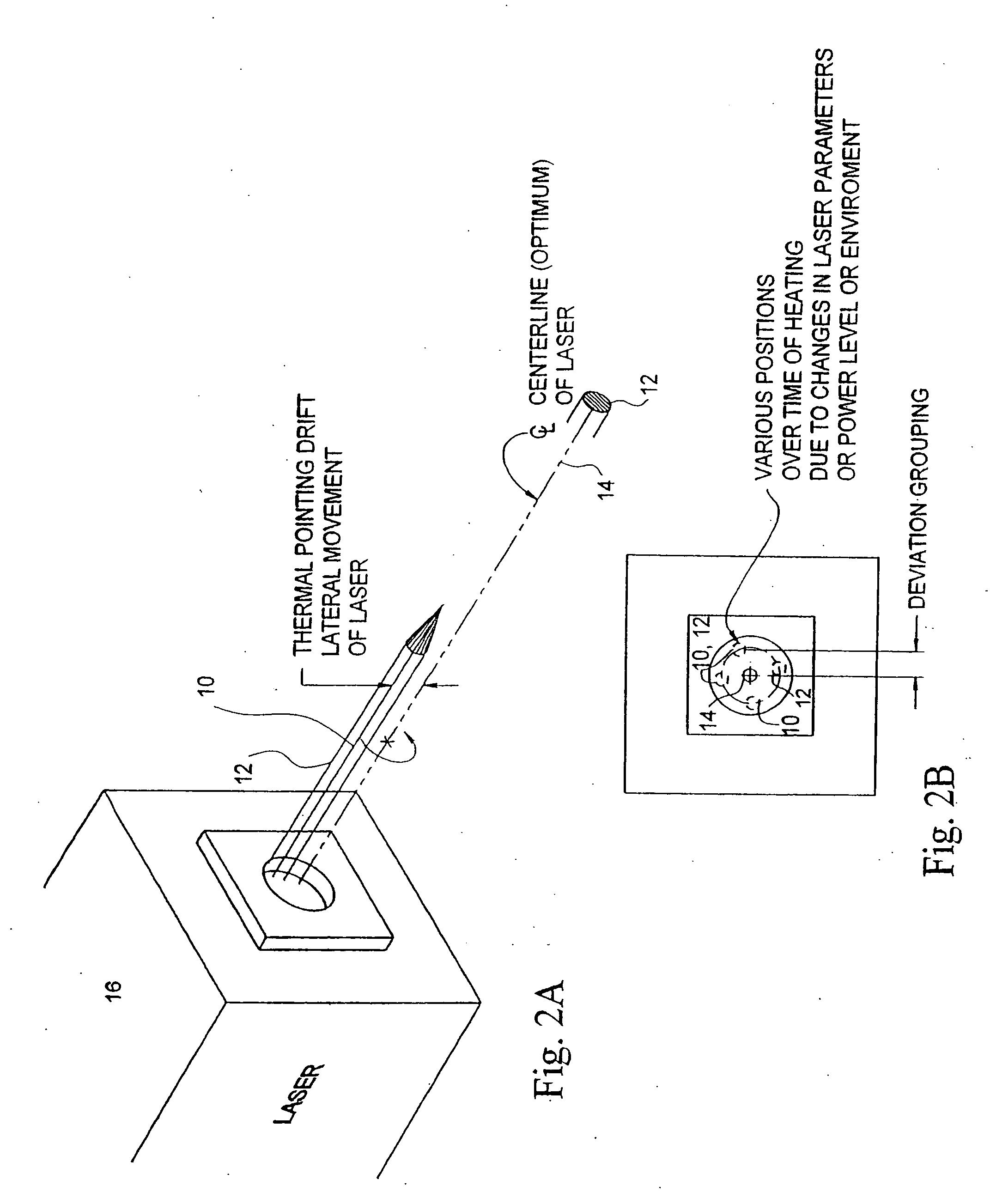
This problem is further compounded, of course, by pointing instabilities and thermal drift.
Effectively all lasers used for micro-machining, such as microvia drilling, exhibit pointing instability, thermal drift and profile distortion, and there have been many attempts to correct or at least control these problems.
Such methods, however, require detecting and comparing the actual path of a beam due to pointing instability or thermal instability with the desired optimum path for the beam and controlling the servo-mirrors so as to direct the beam into the desired path.
Not only are such methods complex and expensive, but they have an inherent time delay in detecting and correcting the effects of pointing instability or thermal drift, and introduce errors of their own due to mechanical and control system tolerances and have thereby not provided completely satisfactory solutions to these problems.
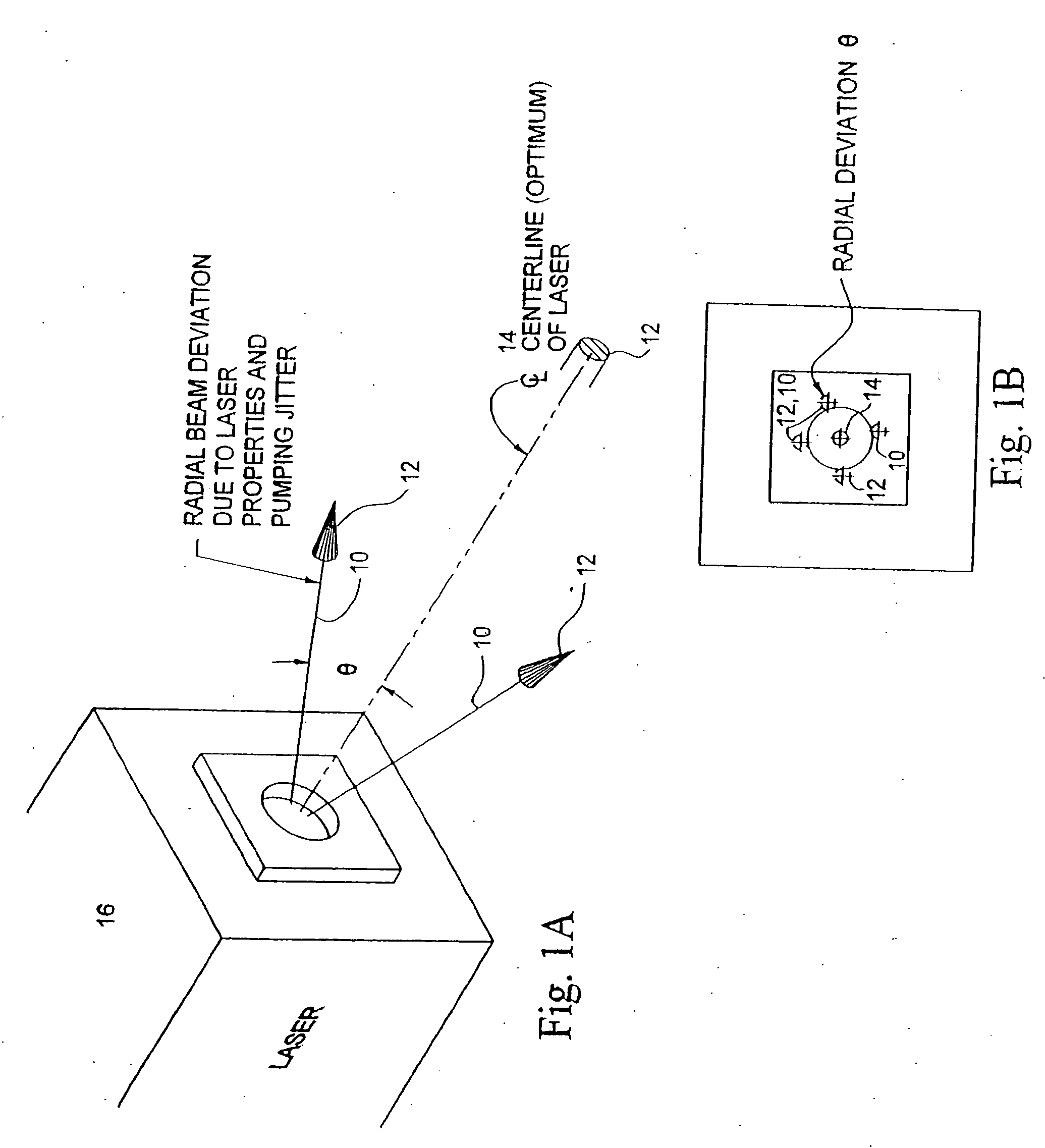
A recurring problem, however, is that when the an optical beam shaping system is illuminated poorly, that is, either at an incident angle or with a laterally displaced beam, such as may result from pointing instabilities, thermal drift or hot spots, the optical beam shaping elements are not able to shape the laser beam into the desired profile.
As in the case of thermal drift, therefore, conventional SSHOEs 18 and similar symmetric lenses cannot correct for or control pointing instability and the resulting angular deviation of the Beam Axis 10.
Instability and shifting in the input beams to beamshifting elements, however, can frequently lead to yet other problems in typical beam delivery systems, such as a micro-machining system for the drilling of microvias, by distortion of the laser beams generated by the beamshaping optics of the system.
Such distortions in the energy profiles of the Output Beam 12O obviously degrade the performance of a laser beam delivery system such as a laser micromaching system.
It will be appreciated that the need to realign the laser beam system optics or the laser beam for each lateral shift of the laser beam, regardless of the cause of the shift, will be a significant problem as an industrial laser system on the production floor will typically, and for example, require realignment several times a day or even several times a work shift.
Such optical elements typically have fixed characteristics that, because they are fixed while the possible lateral shifts of a laser beam are not fixed, may not be able to adequately address the full range of possible lateral shifts of a laser beam in a given system.
This lateral shift creates a problem for an industrial laser system on the production floor, since every time the beam laterally moves, the beam shaping optics generate a hot spot on side or direction that the beam shifts.
This is a considerable problem when a production laser system has to change parameters several times a day or even several times per work shift of operation.

Method used


Image

  • Beam shaping prior to harmonic generation for increased stability of laser beam shaping post harmonic generation with integrated automatic displacement and thermal beam drift compensation
  • Beam shaping prior to harmonic generation for increased stability of laser beam shaping post harmonic generation with integrated automatic displacement and thermal beam drift compensation
  • Beam shaping prior to harmonic generation for increased stability of laser beam shaping post harmonic generation with integrated automatic displacement and thermal beam drift compensation

Examples


second embodiment

[0054]As illustrated generally in FIGS. 6 and 6A through 6F, either or both of radial displacement due to thermal drift and angular deviation due to pointing instability may be corrected by means of a Non-Symmetric Element (NSE) 28 as illustrated in FIG. 6. As illustrated therein, an NSE 28 may be, for example, a Non-Symmetric Hologram Optical Element (NSHOE) or an equivalent optical element, such as a non-symmetric lens or a non-symmetric refraction element or a non-symmetric diffraction element. As indicated, an NSE 28 differs from a SSHOE 18 or equivalent symmetric element in that the path of the Beam Axis 10 of a Laser Beam 12 traversing the NSE 28 is refracted, or turned, through a Correction Angle φ during the passage of the Laser Beam 12 through the NSE 28. As will be discussed further in the following, in one embodiment of a NSE 28 the angle φ increases with increasing radial displacement Δ of the incident Beam Axis 10 from the Centerline Axis 28C of the NSE 28. In a NSE 28,...

first embodiment

[0060]In either instance, and as may be seen from the above discussion of angular deviation geometry, the magnitude of the Correction Angle φ must therefore increase with either increasing radial displacement Δ or with decreasing angle of incidence α. In an Angular Correction NSE 28A, therefore, the Angular Correction NSE 28A, which may be, for example, a NSHOE or equivalent non-symmetric lens, is designed such that the Correction Angle φ increases proportionally to the radial distance from the central axis of the Angular Correction NSE 28A. As described, therefore, the greater the angular deviation θ of a Beam Axis 10 the greater the radial displacement Δ of the Beam Axis 10 from the central axis of the Angular Correction NSE 28A and the greater the Correction Angle φ.

[0061]In a second embodiment of an Angular Correction NSE 28A, the Angular Correction NSE 28A may be designed such that the Correction Angle φ increases with a decreasing angle of incidence α, that is, with an increas...


PUM

PropertyMeasurementUnit
angle of incidenceaaaaaaaaaa
distanceaaaaaaaaaa
wavelengthaaaaaaaaaa

Abstract

A harmonic generation/beam shaping system to generate a shaped beam having a harmonic relationship with a beam generated by a laser, including a first harmonic generation element and a second harmonic generation element arranged sequentially along an axial beam path extending between an input from the laser and an output of the harmonic generation/beam shaping system and at least two beam shaping elements located along the axial beam path. At least one of the least two beam shaping elements is located between the second harmonic generation element and the laser to transform the beam energy profile into a preferred profile to distribute the beam energy across a larger cross sectional area of at least one harmonic generation element or to reduce peaks in the energy distribution profile of the beam, or both, wherein the preferred profile may be a flat-top profile or a Bessel function profile.

Description

CROSS REFERENCE TO RELATED APPLICATIONS[0001]The present invention is a continuation-in-part of and claims benefit of presently pending U.S. patent application Ser. No. 11 / 259,531 filed Oct. 26, 2005 by Todd E. Lizotte for BEAM SHAPING PRIOR TO HARMONIC GENERATION FOR INCREASED STABILITY OF LASER BEAM SHAPING POST HARMONIC GENERATION WITH INTEGRATED AUTOMATIC DISPLACEMENT AND THERMAL BEAM DRIFT COMPENSATION and of U.S. Patent Application Serial No. 11 / 020,914 filed Dec. 22, 2004 by Todd E. Lizotte RADIALLY NON-SYMMETRIC BEAM FORMING ELEMENTS FOR CORRECTION OF ENERGY PROFILE DISTORTIONS DUE TO LATERAL BEAM DRIFT and of U.S. Provisional Patent Application Ser. No. 60 / 624,721 filed Nov. 3, 2004 by Todd E. Lizotte for BEAM SHAPING PRIOR TO HARMONIC GENERATION FOR INCREASED STABILITY OF LASER BEAM SHAPING POST HARMONIC GENERATION WITH INTEGRATED AUTOMATIC DISPLACEMENT AND THERMAL GAIN DRIFT COMPENSATION, and of U.S. patent application Ser. No. 10 / 958,712 filed Oct. 5, 2004 by Todd E. LIZ...

Claims


Application Information

Patent Timeline
Patent Type & Authority Applications(United States)
IPC IPC(8): G02F1/35
CPCG02B27/0927H01S3/005G02F2001/372G02F1/37G02F1/372
Inventor LIZOTTE, TODD E.
Owner HITACHI SEIKO LTD
Why Eureka
Try Eureka