Time modulation array antenna system with reconfigurable frequency and beam direction

A beam direction and time modulation technology, applied in diversity/multi-antenna systems, antennas, antenna arrays, etc., can solve the problems of complex systems, difficult to effectively reflect performance, and high time complexity of algorithms, and achieve simple hardware structure, simple control, The effect of strong compatibility

Inactive Publication Date: 2013-01-02
CHINA RAILWAY SIGNAL & COMM
View PDF4 Cites 34 Cited by
  • Summary
  • Abstract
  • Description
  • Claims
  • Application Information

AI Technical Summary

Problems solved by technology

However, this requires the introduction of hardware such as variable gain amplifiers and multi-bit phase shifters, which often makes the system too complex; in addition, the beamforming algorithm has a high time complexity, and it is difficult to effectively reflect the performance under the actual base station distance and train speed

Method used


Image

  • Time modulation array antenna system with reconfigurable frequency and beam direction
  • Time modulation array antenna system with reconfigurable frequency and beam direction
  • Time modulation array antenna system with reconfigurable frequency and beam direction

Examples


Embodiment 1

[0050] Embodiment 1 Doppler Frequency Shift Compensation and Beam Steering of Time Modulated Array Antenna System Based on Reconfigurable Frequency and Beam Direction

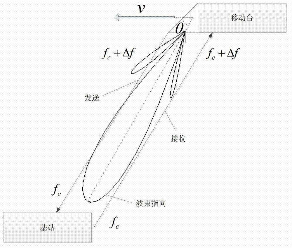
[0051] In this embodiment, the speed v of the mobile station is 150 m / s (520 Km / h), and the angle between the direction of the speed and the direct connection line between the mobile station and the base station is 20°. The array adopts a uniformly distributed linear array, the number of array elements is N=10, and the spacing between array elements is half a wavelength. The carrier center frequency of the transmitted signal is 2GHz. Using a digital frequency synthesizer to set the control frequency f of a high-speed radio frequency switch p = 408.08Hz.

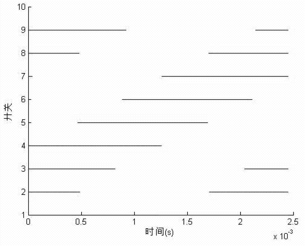
[0052] image 3 It is a timing diagram of the working state of the two-bit phase shifter on each array element branch in one control cycle. Figure 4 This is the beam pattern of the entire antenna under timing control in this working state. It can be seen ...


PUM


Abstract

The invention relates to a time modulation array antenna system with reconfigurable frequency and beam direction, which comprises a control circuit for changing the work state time sequence of two bit phase shifters in a period so as to change the beam direction to trace mobile objects and changing the time modulation period so as to change the beam frequency to complement Doppler frequency shift; two bit phase shifters for periodically maintaining or reversing signals so that the beam energy is concentrated for a primary harmonic component for communication. According to the invention, Doppler frequency shift generated by high speed movement is complemented by changing time modulation period, and the work time sequence of the two bit phase shifters is adjusted to adjust the beam direction and concentrate beam energy to reduce multipath effect. The invention is particularly applied to the field of communication in high-speed movement environments such as railway, airplane and the like.

Description

technical field [0001] The invention relates to the technical field of antenna engineering, in particular to a time-modulated array antenna system capable of reconfiguring beam frequency and direction. Background technique [0002] With the popularization of high-speed railway in our country, it is more and more urgent to meet the communication needs in the high-speed mobile environment. As the vehicle speed continues to increase to 380 or even 500 kilometers per hour, the current mainstream communication system and the 3G-LTE and 4G standards that are about to be put into use can no longer work normally under the existing transceiver antenna mode. The channel characteristics of high-speed mobile trains are multipath propagation and multipath fading, Doppler frequency shift and Doppler spread, ping-pong effect of handover, and forward interference. For example, in engineering applications, due to the large beam coverage angle of the flat-panel antenna still used, in areas w...

Claims


Application Information

Patent Timeline
Patent Type & Authority Applications(China)
IPC IPC(8): H01Q21/00H01Q25/00H04B7/04
CPCY02D30/70
Inventor 连文昭曾润郝俊张寅侃王力高伟李卫杰贺冲金荣洪耿军平梁仙灵
Owner CHINA RAILWAY SIGNAL & COMM
Why Eureka
Try Eureka