The present invention obtains visual information such as visibility prediction and visibility planning information by determining all light rays passing through each
image plane within the image sequence. The present invention takes
advantage of the fact that in addition to capturing a
discrete set of images, an image sequence also captures a continuous range of camera
viewpoints. These
viewpoints are defined by a collection of all light rays passing through image planes. The visual tunnel analysis of the present invention uses this relationship to obtain visual information from the image sequence. One
advantage of the present invention is that, because the visual tunnel technique is concerned with scene appearance, stereo and scene geometry are not modeled and thus stereo correspondence and other expensive forms of
image processing are not needed. Another
advantage of the present invention is that, unlike techniques that use view interpolation between images (such as a lumigraph technique and
light field rendering), the size of the image sequence does not need to be unnecessarily large. This is because the present invention provides visibility planning information to allow the planning of camera trajectories, thus reducing the number of images contained in the image sequence to those necessary to visualize the scene. The present invention also permits the characterizing of a range of new views that may be predicted from an input camera trajectory.
is that, because the visual tunnel technique is concerned with scene appearance, stereo and scene geometry are not modeled and thus stereo correspondence and other expensive forms of
image processing are not needed. Another advantage of the present invention is that, unlike techniques that use view interpolation between images (such as a lumigraph technique and
light field rendering), the size of the image sequence does not need to be unnecessarily large. This is because the present invention provides visibility planning information to allow the planning of camera trajectories, thus reducing the number of images contained in the image sequence to those necessary to visualize the scene. The present invention also permits the characterizing of a range of new views that may be predicted from an input camera trajectory.
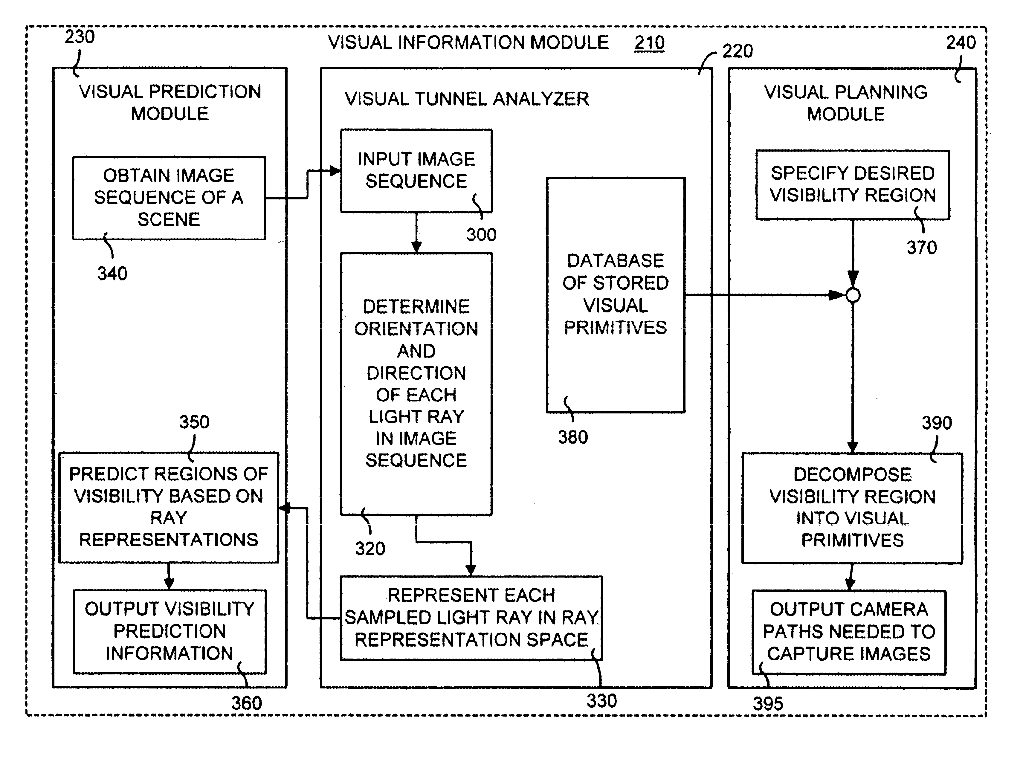
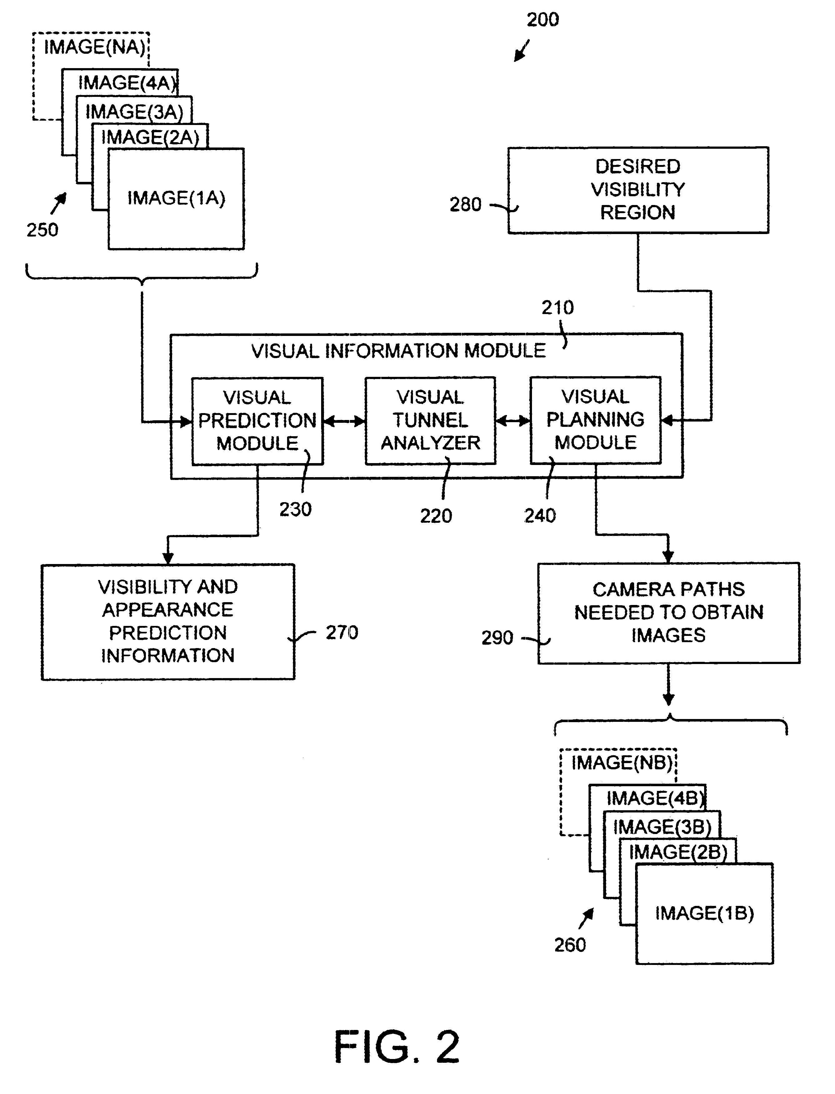
In general, the method of the present invention obtains visual information from an image sequence by using a visual tunnel analysis to determine a position and orientation of each light
ray within the image sequence. This visual tunnel analysis includes defining a visual tunnel and mapping light rays of the image sequence to a
ray space representation within the visual tunnel. Using the visual tunnel, visual information such as visibility prediction and visibility planning may be obtained. For example, a visibility prediction may be obtained as to where a scene may be visualized or a visibility plan may be obtained made as to where an input sequence of images should be captured to obtain a desired
visualization of a scene. In particular, when predicting regions of visibility, the method of the present invention includes obtaining an image sequence, converting the light rays associated with the image sequence into a visual tunnel representation and extracting a region of visibility from the visual tunnel representation. The image sequence is a set of images that captures a portion of the scene appearance and the light rays associated with all the pixels in all the images of the image sequence are converted to a visual tunnel representation. This conversion is accomplished in part by updating the plenoptic function so that, for example, for each light ray, the
Gaussian spheres associated with all points in space that the light ray passes
record the direction of the light ray. In other words, in order to predict regions of visibility in a scene the distribution of the
Gaussian sphere at a location provides the distribution of light rays available to visualize the scene.
When planning a desired
visualization of a scene (also called plenoptic authoring), the method of the present invention includes obtaining an area of interest, computing maximal regions for the area of interest where sampling occurs, determining the combination of visual tunnel primitives that minimally circumscribe the area of interest, and outputting a camera trajectory that will provide the desired
visualization of the scene. The present invention includes a set of visual tunnel primitives that include, for example, concentric mosaics and conic arcs. The area of interest is divided into primitives and a combination of visual tunnel primitives (such as concentric mosaics and straight paths) is assembled to minimally circumscribe the area. Dividing the area into known visual tunnel primitives that minimally circumscribe the area minimizes the number of images needed and provides an efficient camera trajectory. The present invention also includes a
system for obtaining visual information from an image sequence using a visual tunnel analysis that incorporates the above-described method of the present invention.
Other aspects and advantages of the present invention as well as a more complete understanding thereof will become apparent from the following detailed description, taken in conjunction with the accompanying drawings, illustrating by way of example the principles of the invention. Moreover, it is intended that the scope of the invention be limited by the claims and not by the preceding summary or the following detailed description.

