Press brake worksheet positioning system

a positioning system and worksheet technology, applied in forging/pressing/hammering apparatus, forging/hammering/pressing machines, shape safety devices, etc., can solve the problems of physical deterioration of the drive system of the back gauge, out of tolerance of the bend of the parts to be bent, and inability to accurately ascertain the correct positioning of the worksheet. , to achieve the effect of accurate positioning of the worksh

Inactive Publication Date: 2003-11-11
FINN POWER INT
View PDF15 Cites 32 Cited by
  • Summary
  • Abstract
  • Description
  • Claims
  • Application Information

AI Technical Summary

Benefits of technology

To ensure accurate positioning of a worksheet or part for every bend in a press brake, and furthermore without having to worry about the back gauge system becoming inaccurate and / or breaking down, the present invention provides a contactless gauge system that can accurately ascertain the correct positioning of the worksheet for each bend of the worksheet and for compensating any deviation in the positioning of the worksheet.
Yet another embodiment of the present invention involves the use of a combination of laser and imaging systems. In this embodiment, a number of laser beams are directed to the backside of the press brake so as to intersect the back edge of the worksheet. A monitoring camera then senses the multiple points at the edge of the worksheet intersected by the plurality of the laser beams. From these multiple intersected points, the CNC controller can calculate, by for example a triangulation method, the actual position of the worksheet. And by comparing the measured position with the preprogrammed position, any deviation to the positioning of the worksheet that occurs could be readily compensated, before actual bending of the worksheet takes place.
It is therefore an objective of the present invention to provide a system that can monitor without contact the precise location of a worksheet relative to the upper and lower tools of a press brake.
It is another objective of the present invention to provide a contactless worksheet gauge system that obviates the need for any moving system that would cause inaccuracy due to the wear and tear of the mechanical components over time.
It is yet another objective of the present invention to provide a contactless worksheet gauge system that enhances the operation of determining the precise location of a worksheet since the movement of the worksheet no longer has to slow down to make contact with any back gauge fingers.
It is still another objective of the present invention to provide a contactless worksheet position gauging system that can be retrofitted to an existing back gauge system of a press brake.

Problems solved by technology

Moreover, given that the back gauges are driven by multiple servomotors, and their associated motion systems that may include bore screws, belts or linear gear systems for each axis of movement, physical deterioration of the drive system for the back gauges occurs.
As a consequence, the positioning of the parts to be bent may not be as accurate as it should be.
Accordingly, the bends on those parts may end up being out of tolerance.

Method used


Image

  • Press brake worksheet positioning system
  • Press brake worksheet positioning system
  • Press brake worksheet positioning system

Examples


Embodiment Construction

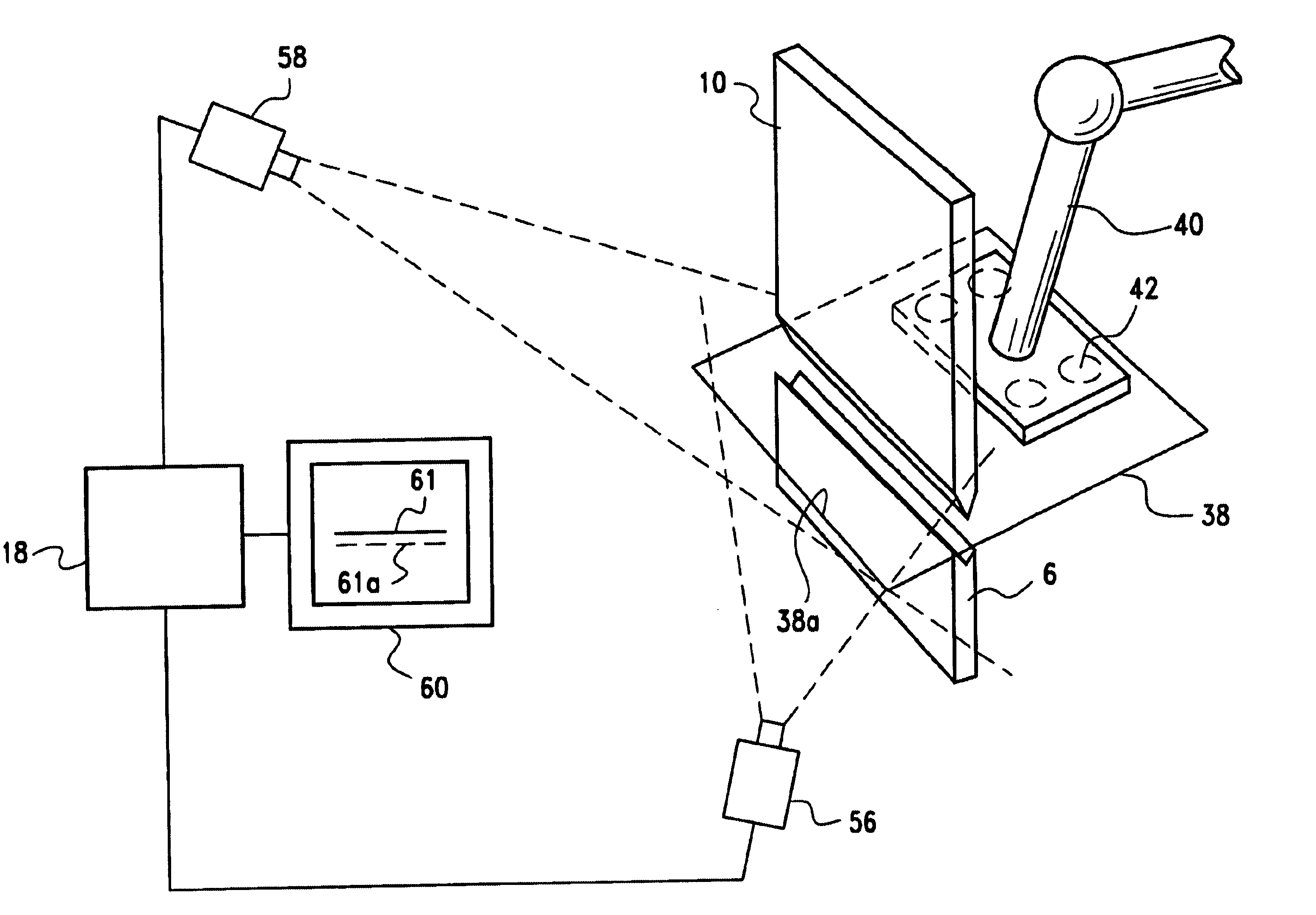
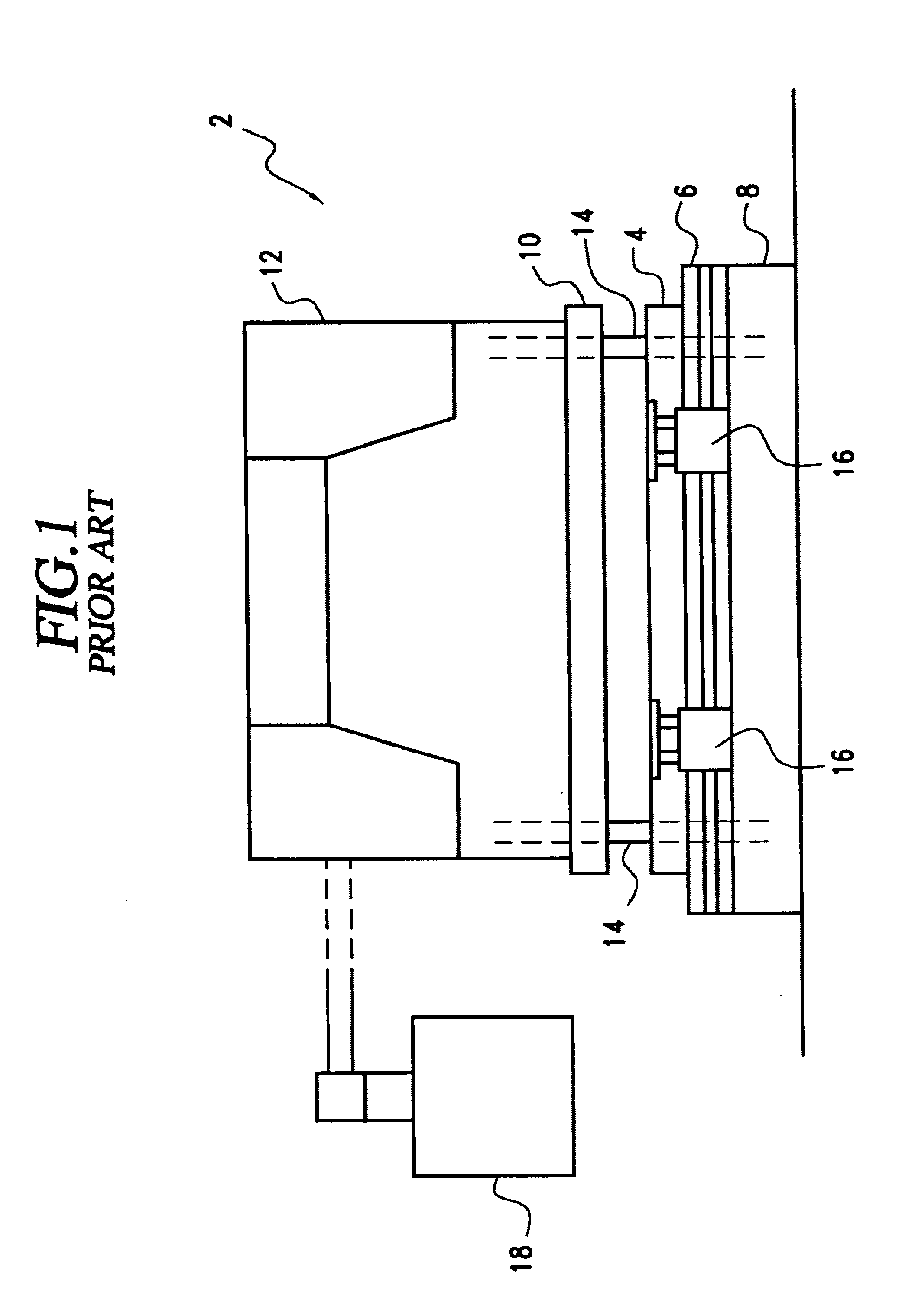
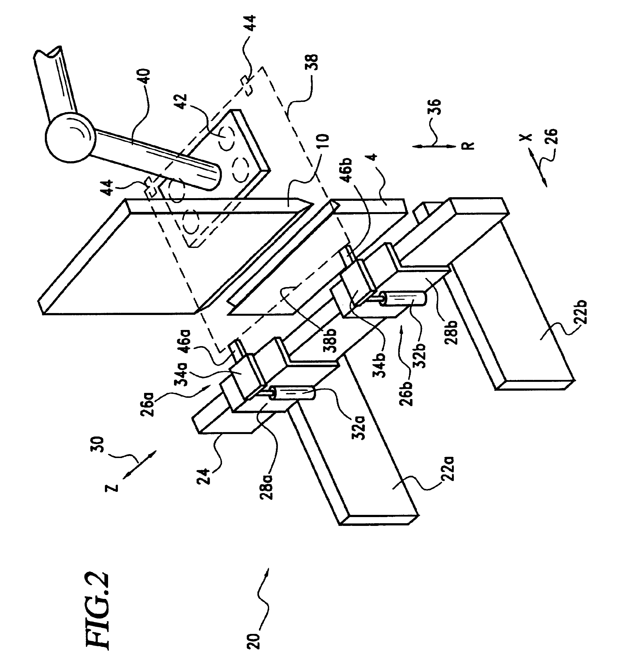
With reference to FIG. 1, a press brake 2 is shown to comprise a lower tool die 4 placed along a die rail 6 on a base 8. Lower tool 4 is a V die which mates with an upper tool punch 10 that is mounted to an upper frame 12. Upper tool 10 is moved vertically to mate with lower tool 4 by drive mechanisms (not shown) that may be mechanical or hydraulic in nature. So, too, lower tool 4 could be driven by mechanical or hydraulic drive mechanisms to press up against upper tool 10. Back frames 14 provide support for press brake 2.

As further shown, in front of rail 6 two supports 16 are movably mounted. Supports 16 provide a rest stop for the front edge of a worksheet positioned into the opening between upper tool 10 and lower tool 4 for bending.

To control the relative movement of upper tool 10 and lower tool 4, electrically connected to press brake 2 is a conventional CNC controller such as for example a DNC 800 controller by the Cybelec S.A. of Switzerland. In fact, press brake 2 as shown ...


PUM

PropertyMeasurementUnit
bendingaaaaaaaaaa
imagingaaaaaaaaaa
distanceaaaaaaaaaa

Abstract

To improve the speed with which a worksheet is positioned in a press brake, and to further eliminate the need for conventional moving back gauge systems, the present invention replaces the conventional back gauge mechanical system with sensors that non-contactedly determine the positioning of the worksheet, with reference to the bending tools. The thus sensed worksheet position is compared with the desired worksheet location preprogrammed into the CNC controller. Any deviation between the sensed, or the actual worksheet position, with the desired worksheet position for each bend of the worksheet is compensated by further moving the worksheet, until there no longer is any discrepancy between the actual and the preprogrammed desired locations.

Description

The present invention is directed to sheet fabrication machines and more particularly to a press brake with an improved sheet positioning system.A typical press brake has a lower tool, typically referred to as a V tool or a die, and an upper tool that acts as a punch that mates with the lower tool. To bend a workpiece placed between the upper and lower tools, the lower tool may remain stationary while the upper tool acts thereagainst. Conversely, the upper tool may stay stationary while the lower tool would move up to act against a worksheet. These up and down motions by the upper and lower tools of the press brake are accomplished by using a number of known drive mechanisms, including for example a hydraulic drive by using one or more hydraulic cylinders, or a mechanical drive that utilizes a combination clutch and brake fly wheel system.To bend a worksheet correctly, the worksheet has to be positioned to the correct position for each of the bends. Conventionally, positioning is de...

Claims


Application Information

Patent Timeline
Patent Type & Authority Patents(United States)
IPC IPC(8): B21D5/00
CPCB21D5/002
Inventor LINDSTROM, MIKKO
Owner FINN POWER INT
Why Eureka
Try Eureka