Element for belt for continuously variable transmission

a technology of continuous variable transmission and belt, which is applied in the direction of driving belt, metal-working apparatus, domestic applications, etc., can solve the problems of belts which are traveling between the pulleys and are liable to be twisted, enlarging the upper portion of the body and hence increasing the thickness,

Inactive Publication Date: 2003-11-11
HONDA MOTOR CO LTD
View PDF7 Cites 8 Cited by
  • Summary
  • Abstract
  • Description
  • Claims
  • Application Information

AI Technical Summary

Benefits of technology

When a plurality of produced elements are stacked into an annular shape for use as a belt for a continuously variable transmission, the neck and the body that are as thick as or thinner than the head allow the belt to bend smoothly radially inwardly, and the elements are kept in a well stacked state without the danger of becoming closer together at the heads. When the belt is trained around pulleys of the continuously variable transmission, the belt is prevented from being displaced radially outwardly, but permits the transmission of stable power in the continuously variable transmission without damage to endless rings inserted in recesses defined in the elements and also to the elements. When the elements are stacked into the annular shape, since relatively thick regions of the elements, i.e., the laterally spaced side end regions of the head and the lower region of the neck, contact those of adjacent ones of the elements, the elements are maintained in a highly stable stacked state. The belt for use in the continuously variable transmission is prevented from traveling in a tortuous path, but can transmit power efficiently.
With the above method, the excess amount of metal produced when the substantially half lower portion of the body is pressed into the thin region by the forming punch is caused to flow into the metal sheet between the body and the head under the counter load applied by the counterpunch, and thereafter the metal sheet into which the excess amount of metal has flowed is separated from the body. Therefore, the excess amount of metal does not remain in the body and hence does not enlarge the body, and the body is prevented from unduly increasing in the thickness. The excess amount of metal produced in the lower region of the neck in the substantially upper half portion of the body is displaced into and distributed in the neck, and any metal flow into the metal sheet to be separated is small. The thickness of the laterally spaced side end regions of the body which are positioned on opposite sides of the lower region of the neck in the substantially upper half portion of the body is easily made smaller than the lower region of the neck in the substantially upper half portion of the body.
Since the excess amount of metal produced in the body is easily caused to flow out of the element or distributed in the neck under the pressing load from the forming punch and the counter load from the counterpunch, the thickness of the laterally spaced side end regions of the head can be increased, and the thickness of the body can easily be made smaller than the thickness of the head. At the same time, the thickness of the laterally spaced side end regions of the body which are positioned on opposite sides of the lower region of the neck in the substantially upper half portion of the body is easily made smaller than the lower region of the neck in the substantially upper half portion of the body. When a plurality of such elements are stacked into an annular form as a belt for a continuously variable transmission, the elements are kept in a well stacked state without the tendency to bend toward the heads.
Preferably, the method may further comprise the step of pressing the metal sheet against the die with a pad under a pressing load which is set to allow the excess amount of load produced under the pressing load applied by the forming punch and the counter load applied by the counterpunch to flow from the body. This step allows the excess amount of metal produced in the body to flow smoothly out of the element.

Problems solved by technology

When the substantially half lower portion of the body is pressed into the thin region by the counterpunch, however, an excess amount of metal is forced to flow from the lower portion into the upper portion of the body, thereby enlarging the upper portion of the body and hence increasing the thickness thereof.
With the body being thicker than the head, the elements tend to be held more closely together at their heads than at their bodies while traveling in the path between the pulleys, and are difficult to be kept in a linearly stacked state between the pulleys.
As a result, the belt which is traveling between the pulleys is liable to be twisted, and fails to transmit stable power in the continuously variable transmission.
In addition, the endless rings in the recesses are likely to be forced into contact with the lower edges of the ears, damaging the elements and the endless rings themselves.

Method used


Image

  • Element for belt for continuously variable transmission
  • Element for belt for continuously variable transmission
  • Element for belt for continuously variable transmission

Examples


Embodiment Construction

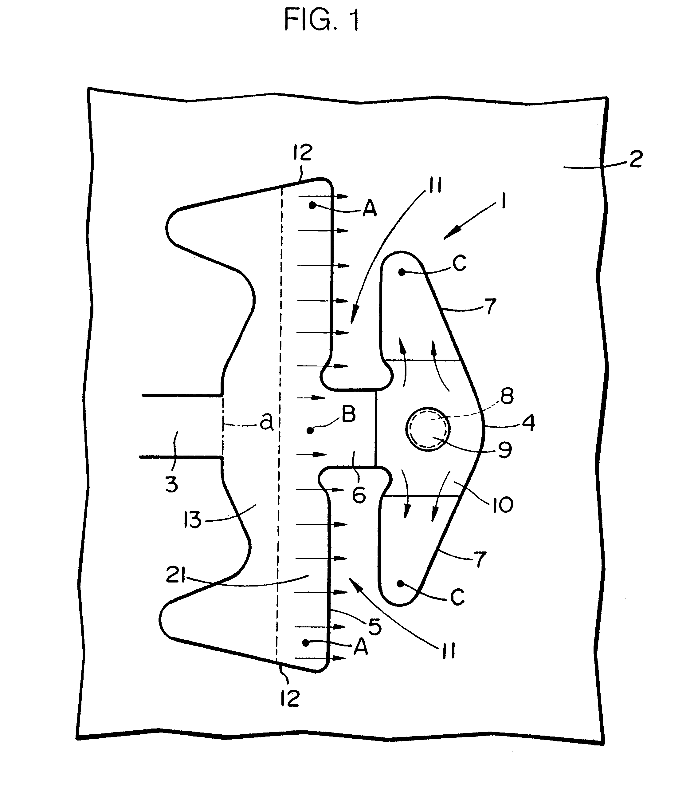
A blanking method according to the present invention is used to manufacture an element 1 (see FIGS. 4(a) and 4 (b)) for a belt for use in a continuously variable transmission (not shown). A plurality of elements 1 are stacked into an annular shape, and bound together by endless rings of metal, thus producing a belt for use in a continuously variable transmission.

As shown in FIG. 1, the element 1 is blanked out of a metal sheet 2. When the element 1 is blanked, it remains connected to the metal sheet 2 by a joint 3. Thereafter, the joint 3 is cut off from the metal sheet 2 along a boundary between the joint 3 and the element 1 as indicated by the imaginary line a in FIG. 1, thus separating the element 1 from the metal sheet 2.

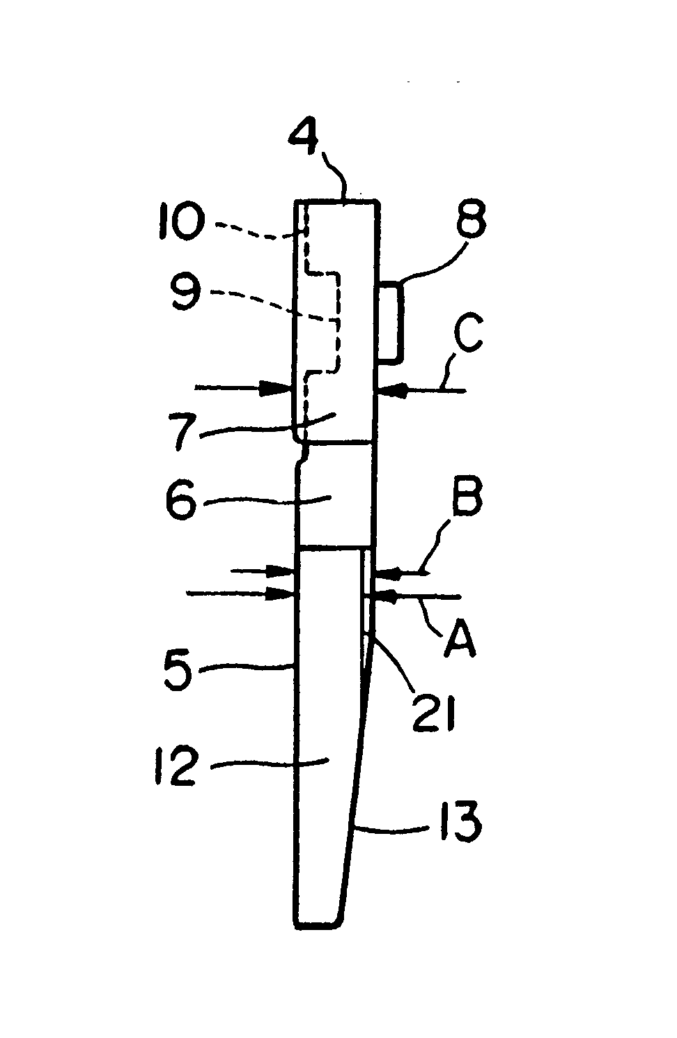
The shape of the element 1 thus blanked and separated will briefly be described below with reference to FIGS. 4(a) and 4(b). The element 1 comprises a head 4 which will be positioned on an outer circumferential edge of the belt for use in the continuously variab...


PUM


Abstract

A body having a thin region in substantially a half lower portion and a head joined to the body by a neck. When the element is blanked out of a metal sheet, an excess amount of metal produced by pressing the substantially half lower portion of the body flows from the body into the metal sheet positioned on an opposite side of the neck and a metal flow is produced into laterally spaced ends of the neck. The head has relatively thick laterally spaced ends and the head and the body have respective thicknesses equal to or smaller than the thickness of the head. The laterally spaced side end regions of the body have a thickness smaller than a thickness of the lower region of the neck in the substantially half upper portion of the body.

Description

1. Field of the InventionThe present invention relates to an element for a belt for use in a continuously variable transmission and a method of blanking such an element out of a metal sheet.2. Description of the Related ArtElements for belts for use in continuously variable transmissions (CVTs) comprise a body having V-shaped surfaces for contact with CVT pulleys and a head joined to an upper edge of the body. The head has a pair of ears projecting laterally away from each other in confronting relation to the upper edge of the body. The ears positioned on the opposite sides of the neck and the body jointly define a pair of recesses therebetween. The body has a thin region in its substantially half lower portion whose thickness is progressively reduced toward a lower edge thereof. A plurality of such elements are transversely stacked in an annular shape and bound together by a pair of endless rings in the form of metal webs that are disposed in the recesses, respectively, thus making...

Claims


Application Information

Patent Timeline
Patent Type & Authority Patents(United States)
IPC IPC(8): B21D53/00B21D53/14F16G5/16F16G5/00
CPCF16G5/16B21D53/14
Inventor SUZUKI, TETSUO
Owner HONDA MOTOR CO LTD
Why Eureka
Try Eureka