Dividing wall column fractionation tray

a technology for dividing wall columns and dividing walls, which is applied in the direction of machine/engine, separation process, combustion air/fuel air treatment, etc., and can solve problems such as interference by downcomers

Inactive Publication Date: 2003-11-11
UOP LLC
View PDF9 Cites 59 Cited by
  • Summary
  • Abstract
  • Description
  • Claims
  • Application Information

AI Technical Summary

Problems solved by technology

The formation of vapor in the downcomer interferes with fluid flow through the downcomer and the separation of vapor and liquid within the downcomer.

Method used


Image

  • Dividing wall column fractionation tray
  • Dividing wall column fractionation tray
  • Dividing wall column fractionation tray

Examples


Embodiment Construction

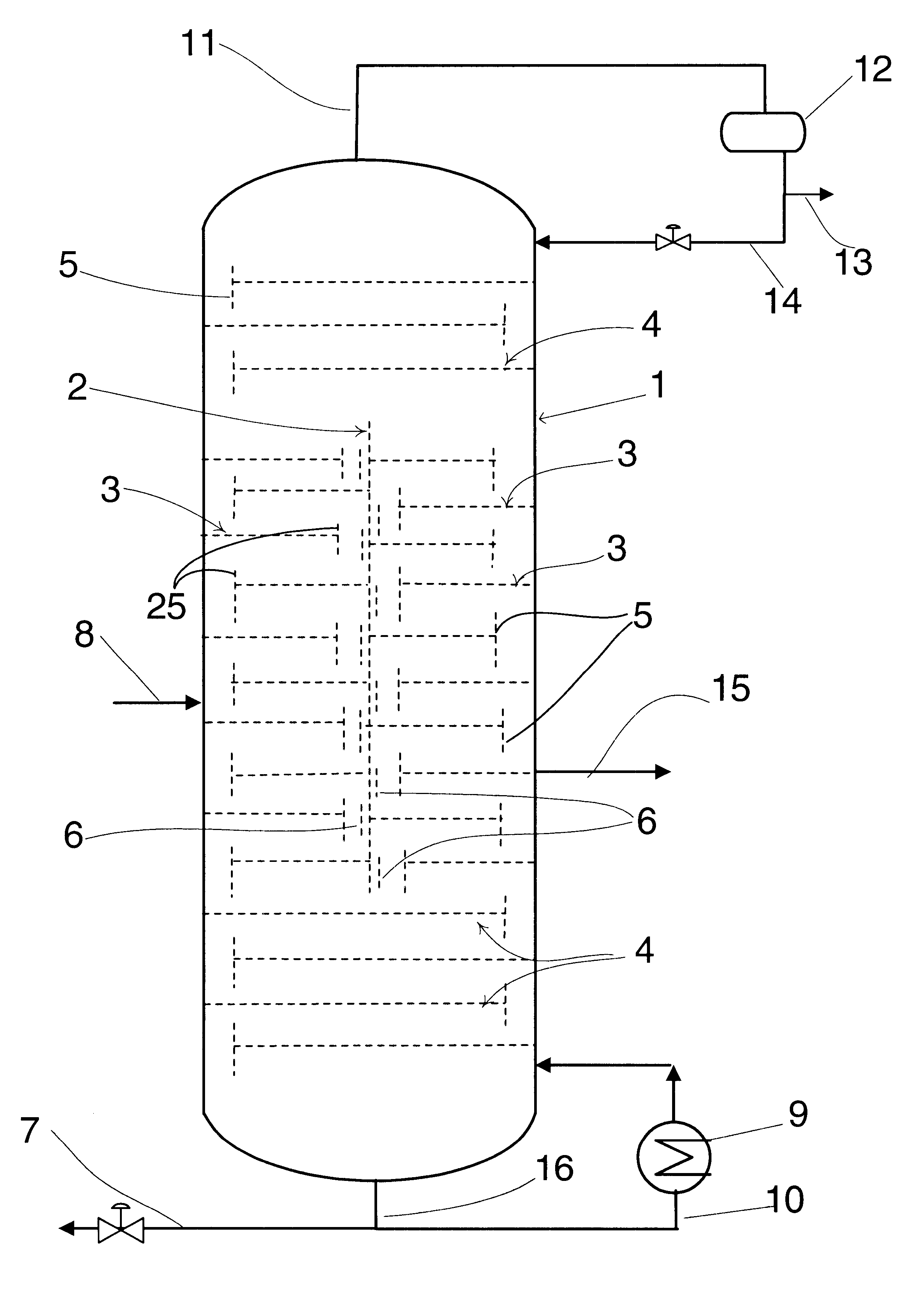
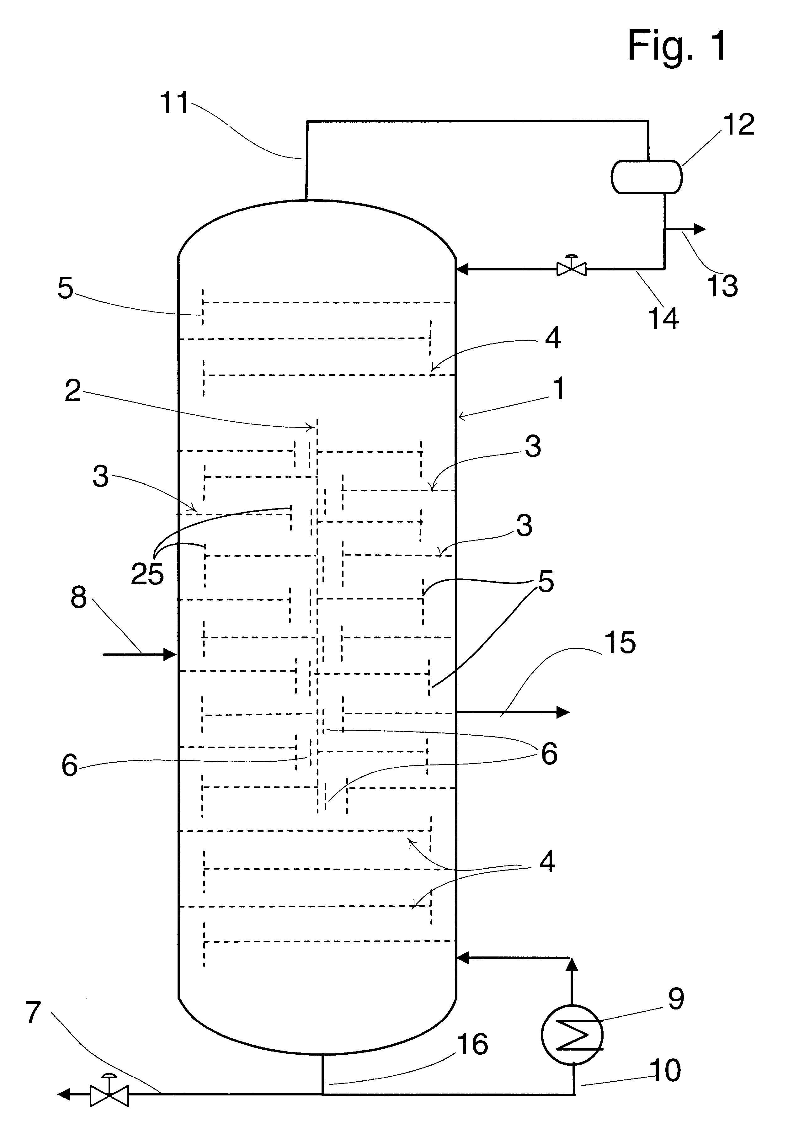
As previously mentioned, fractionation columns find a large utility in many industrial processes. A conventional fractionation column is employed to separate an entering feed stream into two fractions. These are referred to as the overhead and bottoms fraction, with the overhead fraction being the lighter or more volatile components of the feedstream The feedstream may comprise only two components which are separated into high purity streams within the fractionation column. In this instance the overhead stream and the bottoms stream would each be rich in one of the two components of the feedstream. In many instances, however, the feedstream contains three or more compounds and in the instance of petroleum refining processes, the feedstream may contain 100 or 200 or more separate volatile chemical compounds. These mixtures are typically divided by boiling point range into fractions which may each contain numerous different volatile compounds.

In order to separate a feedstream comprisi...


PUM


Abstract

Problems generated by heat transfer through the vertical dividing wall of a trayed "dividing wall column" and into a downcomer of a tray are mitigated by providing a separate vertical isolation wall between the downcomer and dividing wall. The isolation wall forms one side of the downcomer and is spaced a short distance outward from the dividing wall to form an isolation volume which thermally insulates the downcomer from the dividing wall. The added wall is parallel to the dividing wall and supplants the dividing wall as a part of the downcomer. It eliminates a need to insulate the dividing wall.

Description

The invention relates to the design of fractionation trays and columns used to separate volatile chemical compounds by fractional distillation. The invention specifically relates to the design and construction of the downcomers of cross flow trays of a dividing wall fractionation column.Fractional distillation is used to perform a large number of separations of volatile chemical compounds in the chemical, petrochemical and petroleum refining industries. Large scale commercial fractionational distillation is conducted in a vertical enclosed vessel referred to as a fractionation column.The fractionation column will contain some form of vapor-liquid contacting device which may be in the form of packing such as random or structured packing or in the form of a fractionation tray. A fractionation tray typically comprises a large flat area referred to as the decking or contacting deck of the tray plus means to deliver liquid to the tray from the next tray above and to remove liquid for pas...

Claims


Application Information

Patent Timeline
Patent Type & Authority Patents(United States)
IPC IPC(8): B01D3/22B01D3/14B01D3/20
CPCB01D3/14B01D3/22B01D3/20B01D3/141
Inventor STEACY, PAUL C.
Owner UOP LLC
Why Eureka
Try Eureka