External pressure display for vehicle tires

a pressure display and tire technology, applied in vehicle tyre testing, instruments, roads, etc., can solve the problems of bourdon tube mechanism not being well suited to support appreciable magnet masses and friction, hanford device does not include a means of compensating for errors, and fragile bourdon tube gauges

Inactive Publication Date: 2003-11-18
MLHO
View PDF13 Cites 11 Cited by
  • Summary
  • Abstract
  • Description
  • Claims
  • Application Information

AI Technical Summary

Problems solved by technology

Bourdon-tube gauges are fragile, complex, and produce relatively weak forces.
Accordingly, Bourdon tube mechanisms are not well suited for supporting appreciable magnet masses and for overcoming friction.
Accordingly, the Bourdon tube mechanism is necessarily vertically oriented and this type of device is only suited for stationary applications.
Additionally, the Flour Hanford device does not include a means for compensating for errors due to extraneous magnetic fields and does not include a means for extending the operating distance.
Accordingly, such devices generally require careful and extensive calibration before measurements are made.
This type of device typically shares the same problems as the other devices that depend on sensing magnetic field strength.
Disadvantages inherent in this type of device relate to the small distances required between the armature and the magnet, to the small amount of rotational displacement of the magnet produced, and to inadvertent magnetization of the armature.
Disadvantages of these types of devices relate to the need to provide a source of operating power within the pressure container and to inadvertent production of eddy currents in nearby conductive materials that will distort the desired field.
These types of devices do not sense magnetic field direction.
These types of mechanisms are incapable of producing a continuous output responsive to pressure.
None of these types of device employs magnetic coupling for remote sensing.

Method used


Image

  • External pressure display for vehicle tires
  • External pressure display for vehicle tires
  • External pressure display for vehicle tires

Examples


Embodiment Construction

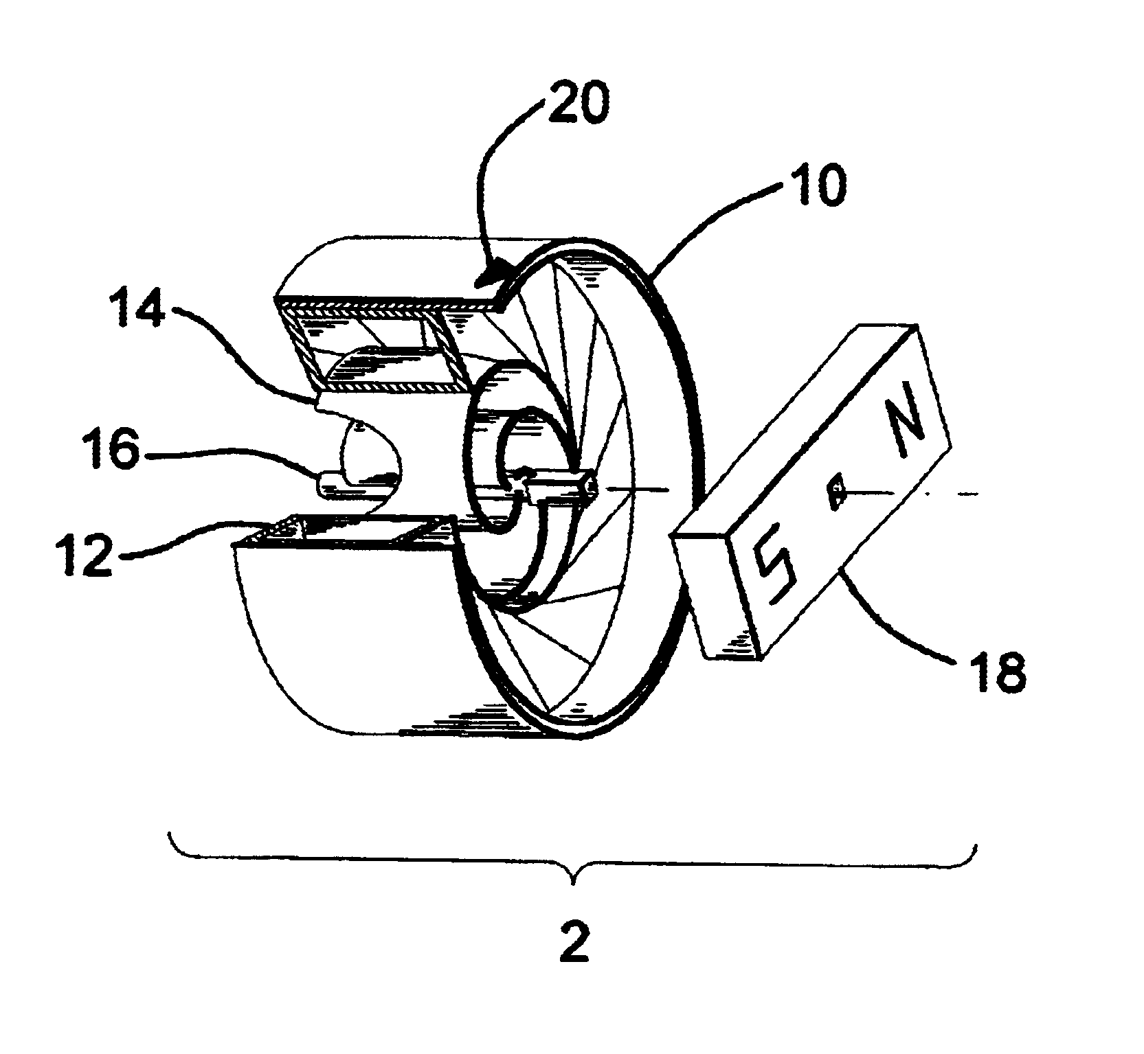
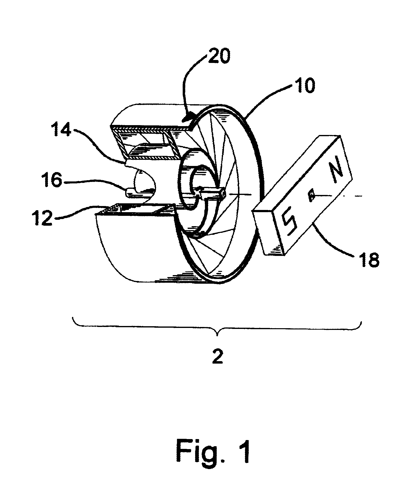
FIG. 1 shows a magnetically coupled pressure sender unit 2. Its principal elements are an outer case 10, a permanently hermetically sealed annular pressure bladder 12, spiral actuating spokes 14, and a shaft 16. Shaft 16 supports a sender permanent magnet 18, which is rigidly attached to and rotates with shaft 16. If three or more spokes 14 are employed, shaft 16 can "float" freely, entirely supported by spokes 14, without bearings. Alternatively, shaft 16 could also be supported by bearings (not shown). Case 10 prevents bladder 12 from appreciably expanding outward and can be used to attach the pressure sender to other objects, such as the inner sidewall of a tire. Case 10 may be part of bladder 12. The entire sender is placed completely inside a pressure vessel (not shown), such as a tire. There is no pressure communication except through external force on bladder 12. Bladder 12 may be pressurized, preferably to ambient pressure, or hold a vacuum. Permanent magnet 18 is depicted a...


PUM


Abstract

A magnetically coupled pressure display system particularly adapted for pneumatic tires of motor vehicles includes pressure transducer coupled for rotating a magnet field source within the tire and an external magneto-optical liquid crystal display attached to or integrally incorporated into the exterior sidewall of the tire for visually indicating pressure within the tire responsive to the orientation of the magnetic field source within the tire. The external display exploits the magneto-optical effects of liquid crystals and can be conformally and permanently attached to the outer tire sidewall surface. Elements (pixels) comprising the display have selective light polarization properties globally determined by direction (orientation) of the magnetic field each experiences, the primary component of which is that provided by the magnetic field source rotated by the pressure transducer within the vehicle tire.

Description

1. Field of InventionThis invention relates to gauging tire pressure without connection to the tire interior, specifically using rotating permanent magnets and a display device that uses magneto-optical effects in liquid crystals or other materials to respond to magnetic field direction.2. Description of Prior ArtFluor Hanford, Inc. has developed a magnetically-coupled pressure readout based on Bourdon-tube principles. Bourdon-tube gauges are fragile, complex, and produce relatively weak forces. Accordingly, Bourdon tube mechanisms are not well suited for supporting appreciable magnet masses and for overcoming friction. In fact, forces generated by the interaction of the earth's magnetic field with a supported magnet can exceed those available from Bourdon tube mechanisms. For readout, the Fluor Hanford device employs a conventional, horizontally oriented, gravity stabilized magnetic compass needle supported by a single-jewel suspension. Accordingly, the Bourdon tube mechanism is ne...

Claims


Application Information

Patent Timeline
Patent Type & Authority Patents(United States)
IPC IPC(8): B60C23/04B60C23/02
CPCB60C23/04B60C23/02
Inventor BURNS, ALAN ALEXANDER
Owner MLHO
Why Eureka
Try Eureka