Radar imaging system and method

a technology of imaging system and camera, applied in the field of imaging system, can solve the problems of poor resolution, degraded cross-range resolution, and difficulty in comparing azimuth data with comparable resolution

Inactive Publication Date: 2003-11-18
RAYTHEON CO
View PDF11 Cites 15 Cited by
  • Summary
  • Abstract
  • Description
  • Claims
  • Application Information

AI Technical Summary

Problems solved by technology

While range data may be resolved with adequate resolution, currently, resolution of azimuth data with comparable resolution has proved to be problematic.
This is due to the fact that azimuth resolution is limited to the width of the antenna beam and the corresponding cross range resolution degrades as a function of range.
Accordingly, the poor resolution of conventional real beam mapping systems limits the ability of the system to discriminate scatterers.
Conventional doppler beam sharpening (DBS) or Synthetic Aperture Radar techniques may be used to improve the azimuth resolution, but these require excessive frame times if the coverage includes regions close to the velocity vector.
However, the quality achieved is scene dependent and is not robust.

Method used


Image

  • Radar imaging system and method
  • Radar imaging system and method
  • Radar imaging system and method

Examples


Embodiment Construction

Illustrative embodiments and exemplary applications will now be described with reference to the accompanying drawings to disclose the advantageous teachings of the present invention.

While the present invention is described herein with reference to illustrative embodiments for particular applications, it should be understood that the invention is not limited thereto. Those having ordinary skill in the art and access to the teachings provided herein will recognize additional modifications, applications, and embodiments within the scope thereof and additional fields in which the present invention would be of significant utility.

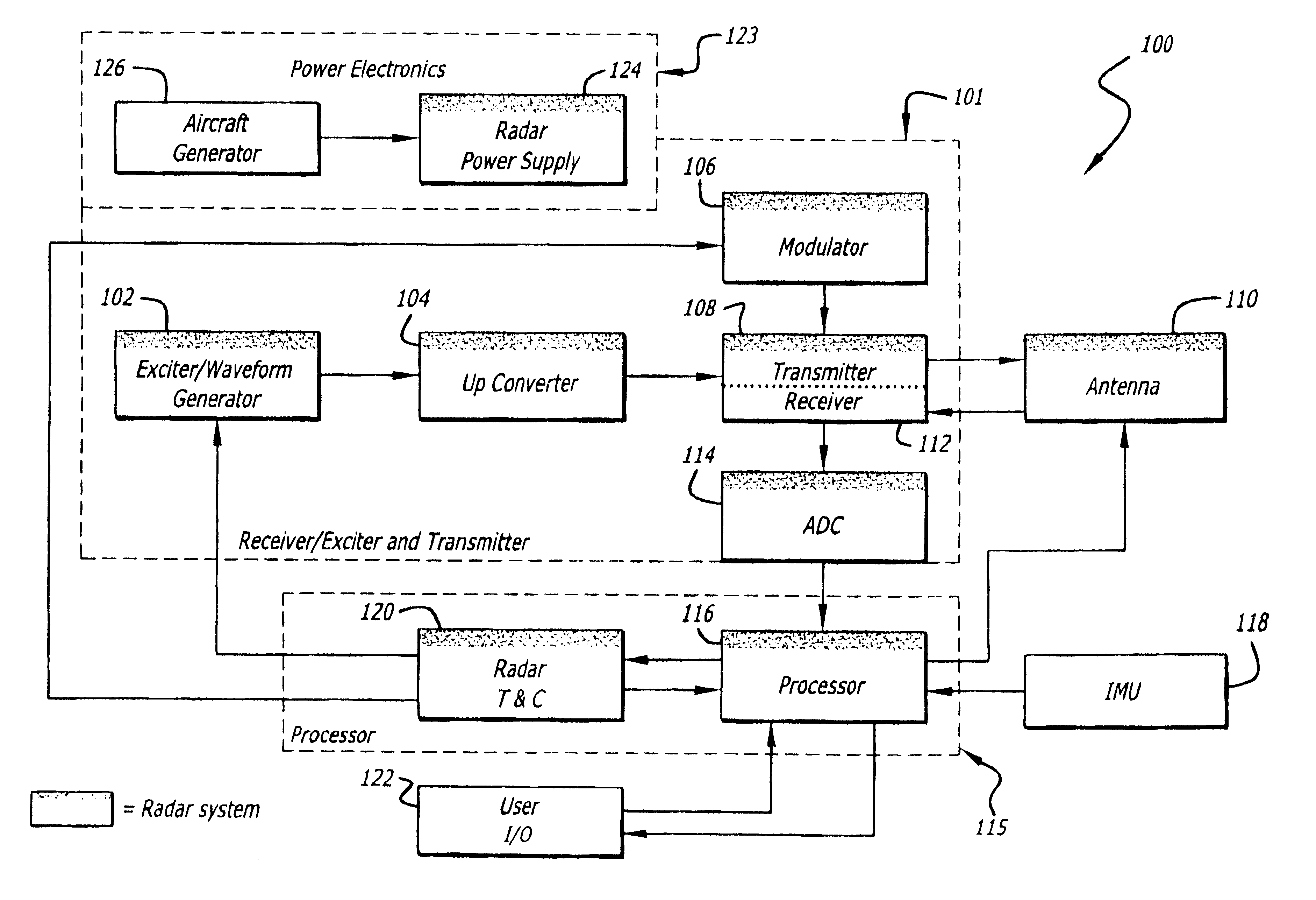
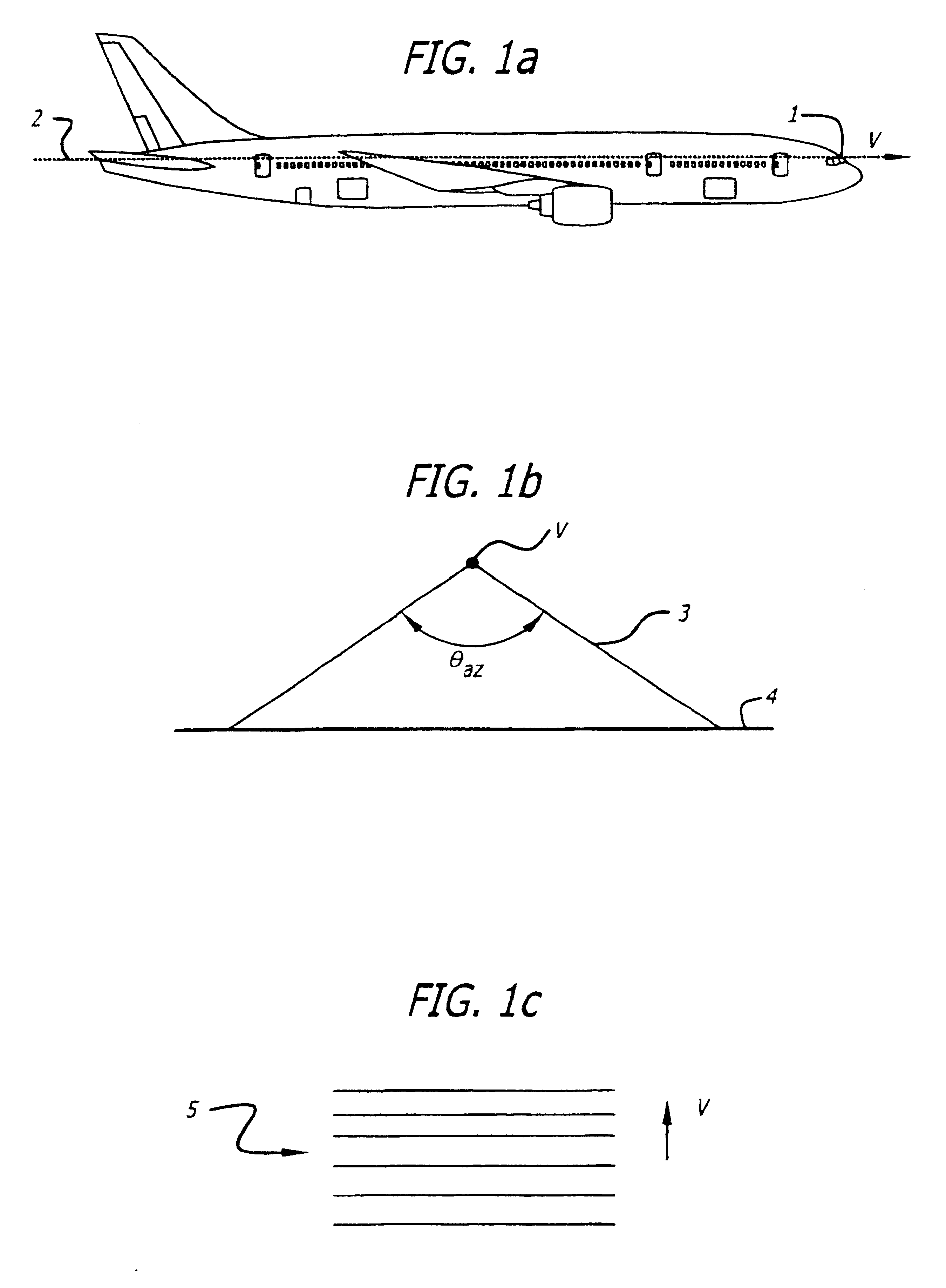
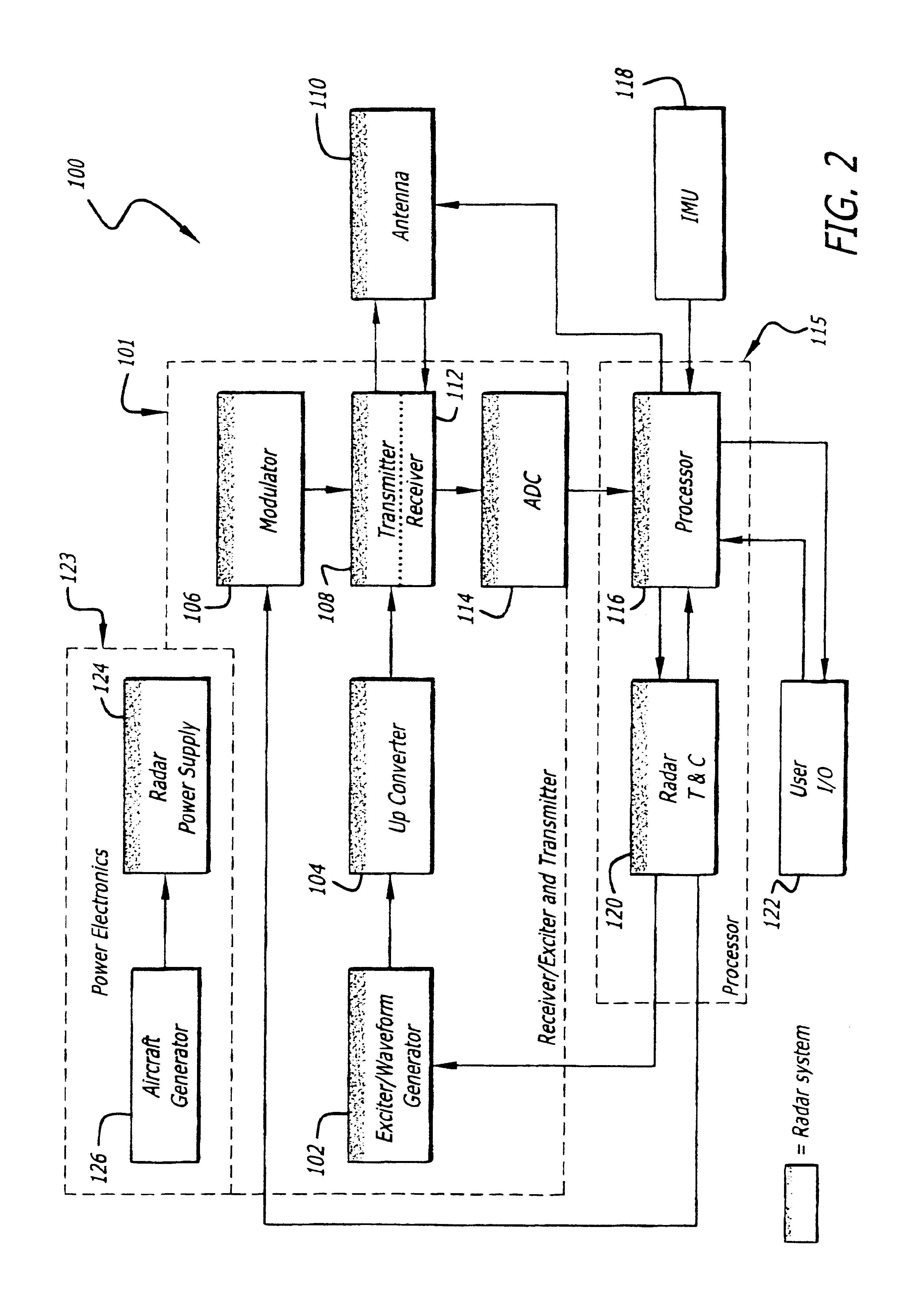
The present invention is adapted for use on a vehicle such as an aircraft moving with a velocity vector such as that shown in FIGS. 1a-c.

FIG. 1a is a side view of an aircraft and flight provided to illustrate the longitudinal axis and velocity vector thereof. As shown in FIG. 1a, the velocity vector V of the aircraft 1 is coincident with the longitudinal axis 2 ...


PUM


Abstract

An imaging system and method. The invention provides an intra-pulse repetition interval (PRI) agile beam technique for enhanced resolution that can be used at aspect angles near the velocity vector of a host vehicle. It is particularly useful at small scan angles where beam sharpening array times become large. At these scan angles, the bandwidth of the clutter is narrower than at higher scan angles and allows large PRIs without degradation from Doppler ambiguities. In accordance with the present teachings, sequential illumination is performed within a PRI to multiple beam locations using an agile beam. The interleaving of beams reduces map formation times compared to conventional techniques using sequential arrays. The inventive system is adapted for use with an electronically scanned (e.g., synthetic aperture array radar) antenna. The inventive method includes the steps of activating the antenna to generate a beam of electromagnetic energy; causing the beam to scan over a predetermined scan volume consisting of a predetermined range of scan angles relative to a reference vector; and generating multiple simultaneous beams of electromagnetic energy over a subset of the predetermined range of scan angles.

Description

1. Field of the InventionThe present invention relates to imaging systems. More specifically, the present invention relates to radar imaging systems.2. Description of the Related ArtImaging techniques are well known and widely used in the art. Certain imaging technologies are better suited for particular applications. For example, radar imagery is widely used for surveillance and reconnaissance as well as target tracking and identification. For radar and other imaging technologies, the ability to clearly resolve and discriminate targets may be essential in meeting objectives specified for a particular application.One such application involves `real beam ground mapping.` Real beam ground mapping involves scanning an area, e.g., the earth's surface, using a scanning antenna or an electronically scanned antenna. Returns from an illumination of the surface are then examined for `back-scatter` or reflections therefrom. As the beam is scanned in azimuth, information is collected with resp...

Claims


Application Information

Patent Timeline
Patent Type & Authority Patents(United States)
IPC IPC(8): G01S13/00G01S13/89G01S13/02G01S13/90G01S13/42
CPCG01S13/89G01S13/426G01S2013/0245G01S13/90
Inventor KRIKORIAN, KAPRIEL V.ROSEN, ROBERT A.
Owner RAYTHEON CO
Why Eureka
Try Eureka