Identifying failures in an aeroengine

a technology of failure detection and aeroengine, which is applied in the direction of program control, total factory control, instruments, etc., can solve the problems of expensive and difficult construction, and achieve the effect of more accurate and robus

Active Publication Date: 2011-12-15
SN DETUDE & DE CONSTR DE MOTEURS DAVIATION S N E C M A
View PDF24 Cites 34 Cited by
  • Summary
  • Abstract
  • Description
  • Claims
  • Application Information

AI Technical Summary

Benefits of technology

[0045]This enables a decision grid to be cons

Problems solved by technology

Furthermore, it is possible to rely on knowledge collected from experts rather than on a

Method used


Image

  • Identifying failures in an aeroengine
  • Identifying failures in an aeroengine
  • Identifying failures in an aeroengine

Examples


Embodiment Construction

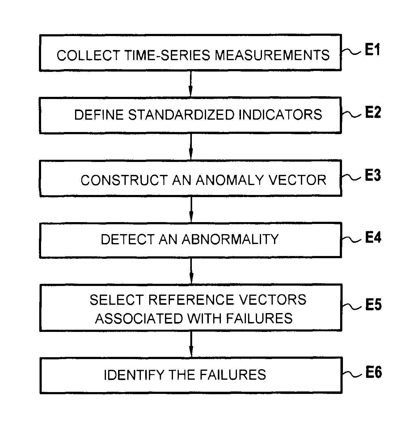
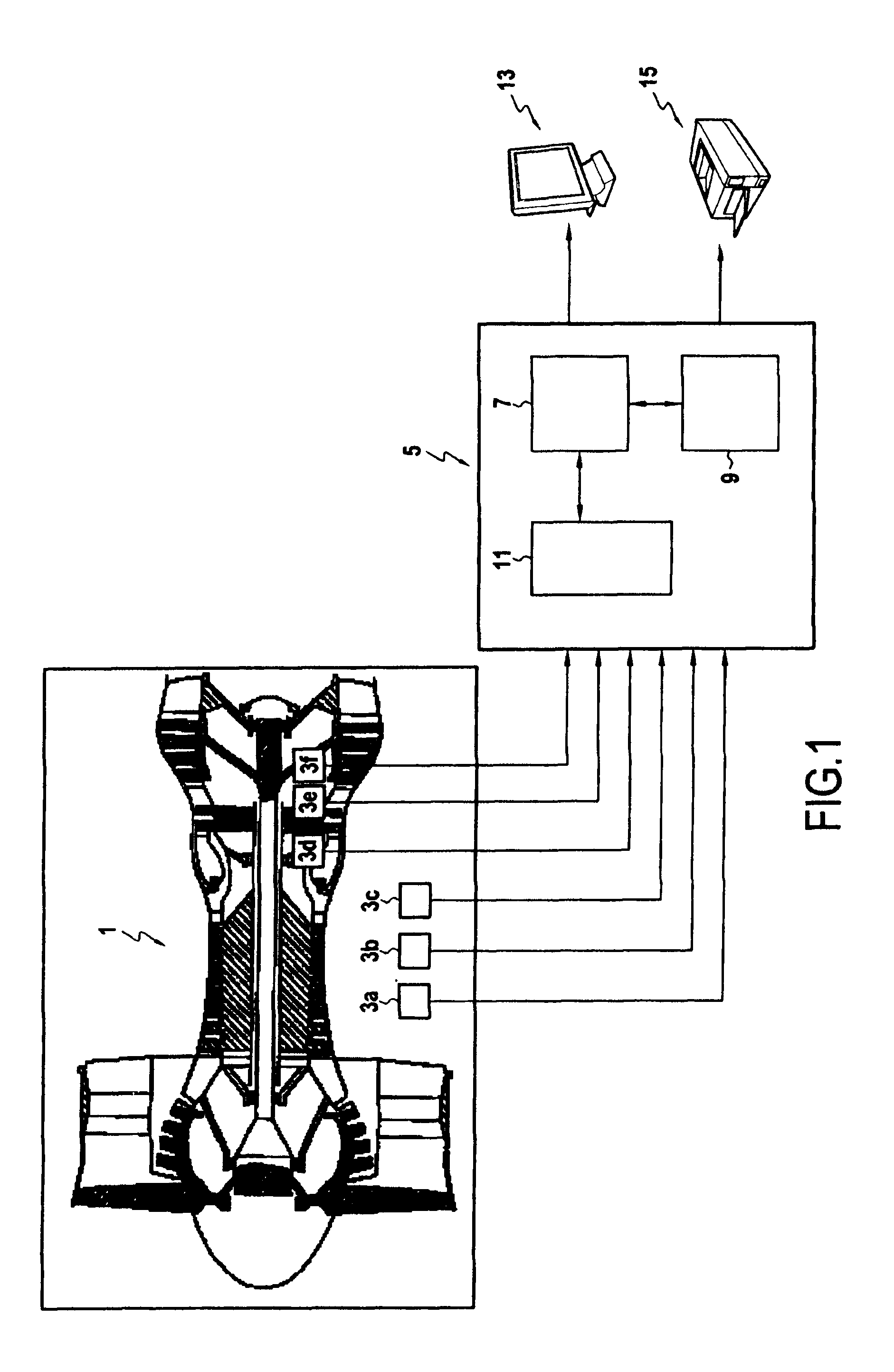
[0056]FIG. 1 shows the hardware means implemented in the system or method of the invention for identifying failures in an aeroengine 1.

[0057]The system comprises a plurality of sensors 3a-3f for measuring time-series data relating to the engine 1 and its environment. The system also includes processor means 5 for processing information such as a calculator or computer suitable for being used to execute a computer program designed to implement the method of the invention. The processor means 5 comprise the hardware means that are conventionally found in a computer. More particularly, these processor means 5 comprise a central unit 7 that executes the instruction sequences of the program of the method of the invention, a central memory 9 that stores the data and programs being executed, storage means or media 11 for storing digital conserving the data, input peripherals (sensors 3a-3f, keyboard, mouse, . . . ) and output peripherals (screen 13, printer 15, . . . ) for delivering the r...


PUM


Abstract

A method and a system for identifying failures in an aeroengine. The system includes: a mechanism defining a set of standardized indicators representative of operation of the aeroengine; a mechanism constructing an anomaly vector representative of a behavior of the engine as a function of the set of standardized indicators; a mechanism selecting in an event of an anomaly being revealed by the anomaly vector a subset of reference vectors having directions belonging to a determined neighborhood of a direction of the anomaly vector, the subset of reference vectors being selected from a set of reference vectors associated with failures of the aeroengine and determined using criteria established by experts; and a mechanism identifying failures associated with the subset of reference vectors.

Description

FIELD OF THE INVENTION[0001]The present invention relates to the field of monitoring an aeroengine. In particular, the invention relates to identifying failures and to detecting faulty components in an aeroengine.[0002]In numerous industries, such as the aviation and space industries, it is important to be able to identify failures of an aeroengine from measurements that describe the instantaneous state of the engine so as to deduce which physical component is faulty, if any.[0003]Nevertheless, such time-series measurements are expressed in a variety of different physical units and they may vary from flight to flight in arbitrary manner, thereby complicating any analysis and processing of such measurements.[0004]So-called “scoring” tools exist that seek to substitute time-series measurements that may be expressed in various different units, with quality scores. Such tools are based on likelihood calculations leading to quality control systems. Nevertheless, scoring tools are difficu...

Claims


Application Information

Patent Timeline
IPC IPC(8): G06F19/00G06F15/18
CPCG05B23/024G05B2219/32201G05B2219/32191G05B23/0281Y02P90/02
Inventor LACAILLE, JEROME
Owner SN DETUDE & DE CONSTR DE MOTEURS DAVIATION S N E C M A
Why Eureka
Try Eureka