Capacitive sensor and method of fabricating

a capacitive sensor and capacitive technology, applied in the direction of fluid pressure measurement, fluid pressure measurement by electric/magnetic elements, instruments, etc., can solve the problems of inapplicability of sealing and strengthening integrated circuits, change etc., to improve mechanical strength, maintain the dielectric gap dimension over time, and less vulnerable to mechanical stress and strain

Active Publication Date: 2006-08-31
ANALOG DEVICES INC
View PDF7 Cites 6 Cited by
  • Summary
  • Abstract
  • Description
  • Claims
  • Application Information

AI Technical Summary

Benefits of technology

[0007] It is a further object of this invention to provide such an improved capacitive sensor which better maintains the dielectric gap dimension over time and temperature.
[0008] It is a further object of this invention to provide such an improved capacitive sensor which better maintains the dielectric gap dimension decoupled from and independent of the effects of creep on conductor elements, e.g. solder balls.
[0009] It is a further object of this invention to provide such an improved capacitive sensor which can endure adverse conditions in fabrication and use.
[0010] It is a further object of this invention to provide such an improved capacitive sensor which is less vulnerable to mechanical stress and

Problems solved by technology

One problem with this construction is that the conductive elements, such a, the solder balls, which contain substantial lead, are susceptible to creep over time and temperature which will change the dimension of the dielectric gap.
The stress and strain endured by the capacitive sensor during fabrication and in use can exacerbate this problem and sometimes cause failure of the solder balls resulting in an open circuit.
Under filling, a technique used to

Method used


Image

  • Capacitive sensor and method of fabricating
  • Capacitive sensor and method of fabricating
  • Capacitive sensor and method of fabricating

Examples


Embodiment Construction

[0035] Aside from the preferred embodiment or embodiments disclosed below, this invention is capable of other embodiments and of being practiced or being carried out in various ways. Thus, it is to be understood that the invention is not limited in its application to the details of construction and the arrangements of components set forth in the following description or illustrated in the drawings. If only one embodiment is described herein, the claims hereof are not to be limited to that embodiment. Moreover, the claims hereof are not to be read restrictively unless there is clear and convincing evidence manifesting a certain exclusion, restriction, or disclaimer.

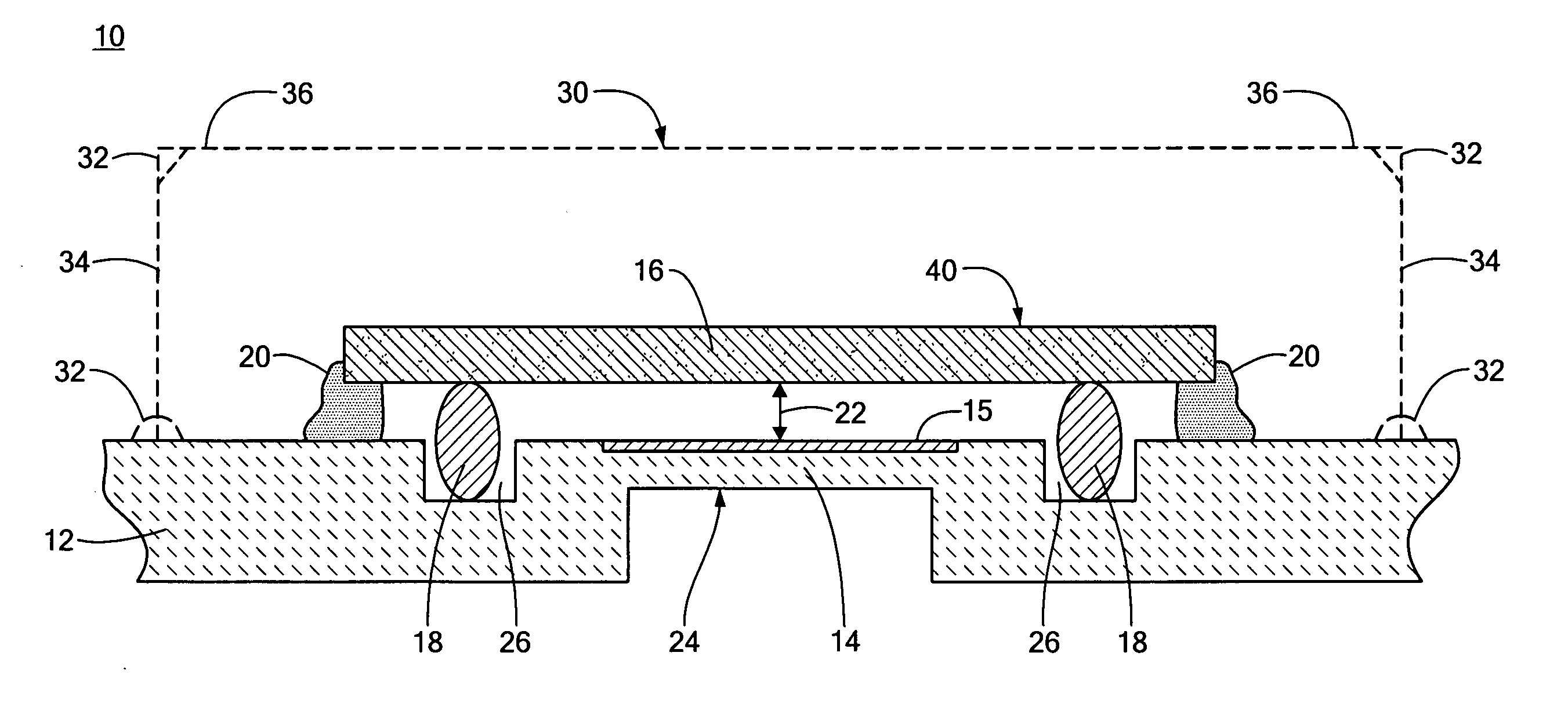
[0036] There is shown in FIG. 1 a capacitive sensor 10 according to this invention including a substrate 12 having formed in it a diaphragm 14 which forms one plate of a capacitor. The other plate of the capacitor is formed by a second, fixed plate 16 which is interconnected with substrate 12 by conductor elements, solder...


PUM


Abstract

A capacitive sensor and a method of making it with a substrate having a diaphragm forming a first plate of a capacitor; a second fixed plate of the capacitor spaced from the diaphragm and defining a predetermined dielectric gap; a plurality of conductor elements interconnecting the substrate and fixed plate; and an edge lock supporting the fixed plate and the substrate relative to each other for maintaining the dimension of the defined gap independent of the conductor elements.

Description

RELATED APPLICATIONS [0001] This application claims the benefit of U.S. Provisional Application No. 60 / 656,238, filed Feb. 25, 2005, incorporated by reference herein.FIELD OF THE INVENTION [0002] This invention relates to an improved capacitive sensor and method for fabricating it and more particularly to such a capacitive sensor with a more reliable capacitive gap dimensions. BACKGROUND OF THE INVENTION [0003] In a capacitive sensor the dielectric gap between the fixed plate and the diaphragm must be strictly maintained if the sensing of the external pressure is to be accurate. Typically the fixed plate may be silicon with signal processing circuits on one side and conductor elements such as solder balls on the other. This fixed silicon plate may be flip chip bonded to a substrate, typically a ceramic material, which contains a diaphragm. External pressure changes on the diaphragm are reflected in changes in the dielectric gap dimension which translates into a change in capacitance...

Claims


Application Information

Patent Timeline
IPC IPC(8): G01B7/16
CPCG01L9/0075
Inventor MEEHAN, PETER G.KIERSE, OLIVER
Owner ANALOG DEVICES INC
Why Eureka
Try Eureka