
Space Vector Modulation for Multilevel Inverters

a space vector and multi-level technology, applied in the field of electric power conversion systems, can solve the problems of reducing the flexibility of the svpwm method

Active Publication Date: 2014-01-16
MITSUBISHI ELECTRIC RES LAB INC
View PDF0 Cites 30 Cited by
  • Summary
  • Abstract
  • Description
  • Claims
  • Application Information

AI Technical Summary

Benefits of technology

The invention provides a method for space vector pulse width modulation (SVPWM) for a multilevel inverter based on a space vector diagram of switching states of the inverter. The method allows for flexibility in designing the inverter of any level and reduces processing time to switch states while minimizing memory requirements. The method also allows for the modification of the reference voltage to achieve feasibility of modulation and reduces the complexity for determining the switching states. Additionally, the method can be extended to generate symmetric switching sequences, control voltage balance of DC link capacitors, and change the switching sequence for other specific requirements.

Problems solved by technology

However as the level of the inverter increases the increased number of triangles, switching states, and calculation of duty cycles enlarges the complexity of SVPWM for multilevel inverters.
However, with the increasing number of levels of the inverter, both of those two methods become intensive in computation.
However, those methods are not readily extended to four or higher level inverters.
Because of the two-phase to three-phase conversion for each partition of the space vector diagram, the complexity and computation of the method are increased when applied to a four or higher level inverter.
Moreover, no general switching sequence selection is used by the method.
However, several matrix transformations are needed, and no systematic approach for determining the switching states or real-time implementation is provided in N. Celanovic's method.
However, because the number of possible switching sequences increases with the increasing level of the inverter, more memory is needed and slower mapping speed is achieved when A. Gupta's method is applied to higher level inverters.

Method used


Image

  • Space Vector Modulation for Multilevel Inverters
  • Space Vector Modulation for Multilevel Inverters
  • Space Vector Modulation for Multilevel Inverters

Examples


Embodiment Construction

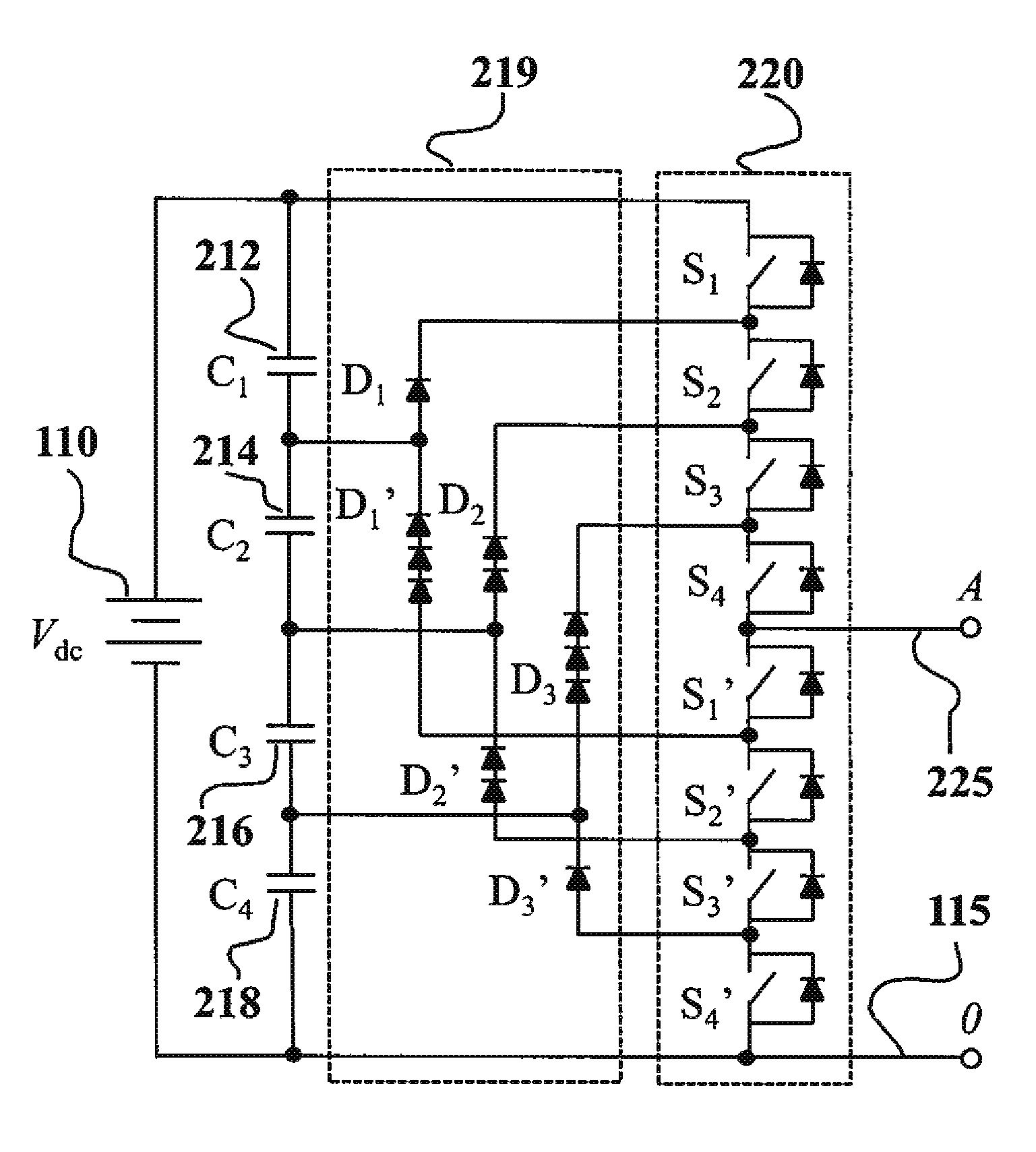
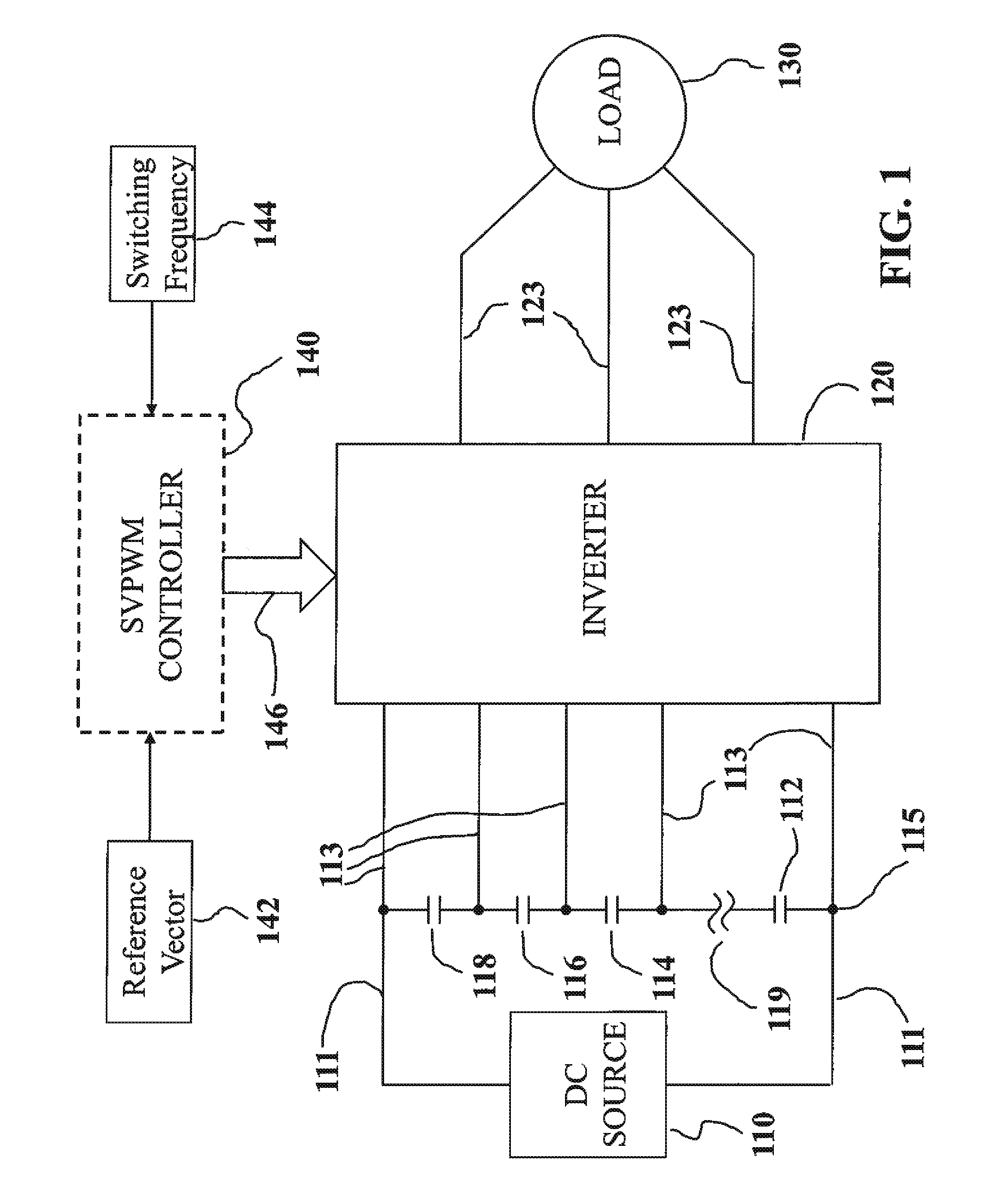
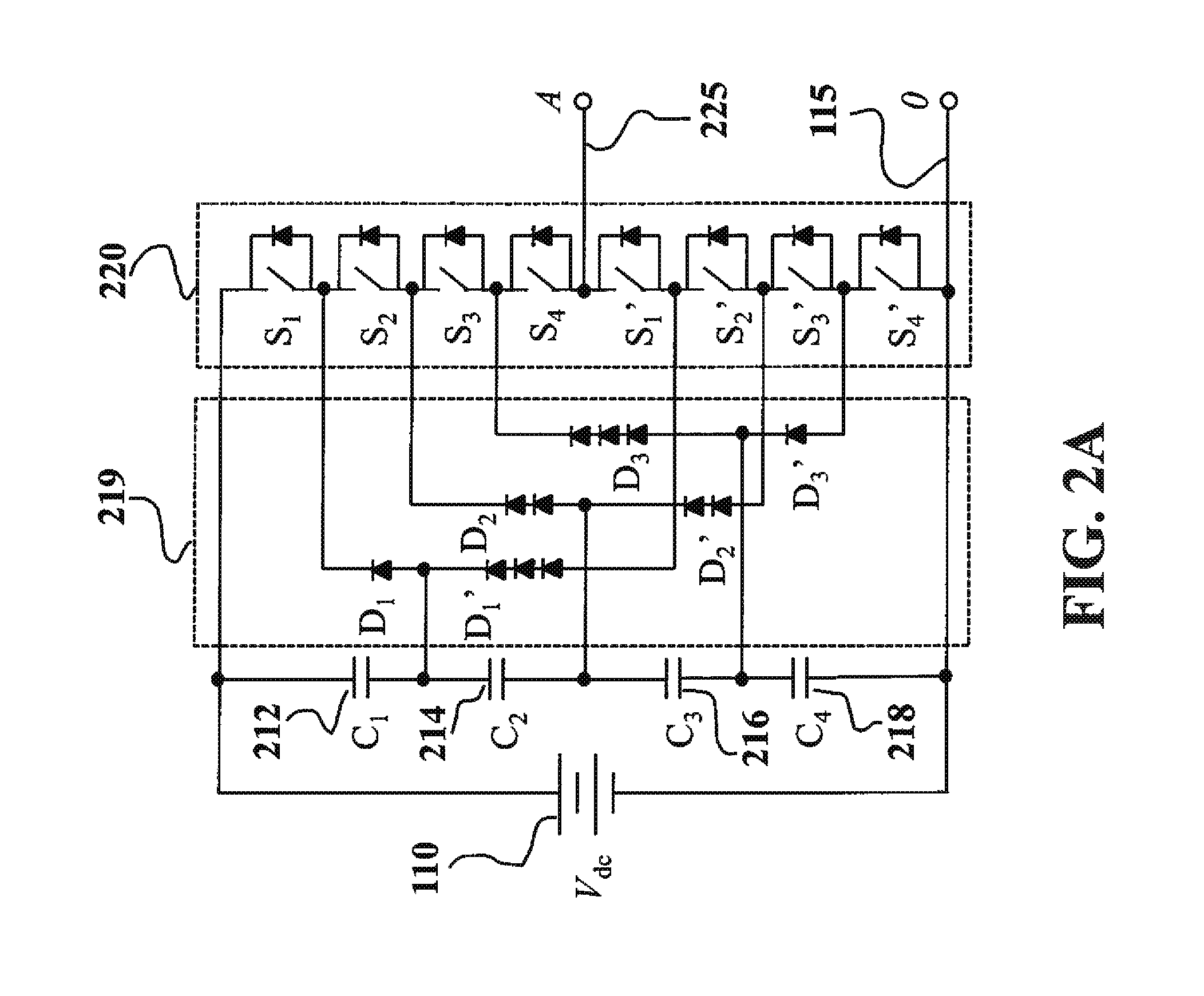
[0047]Multilevel inverters are used in high-power medium-voltage applications due to their superior performance compared to two-level inverters. Space vector pulse width modulation (SVPWM) is preferred for various modulation strategies for multilevel inverters because SVPWM offers significant flexibility to optimize switching waveforms, and because SVPWM is well suitable for digital signal processor implementation. In order to reduce the harmonics and voltage surges during the switching transients, the “Nearest Three Vectors” (NTV), is commonly adopted for SVPWM.

[0048]For an n-level inverter, however, there are n3 switching states and 6(n−1)2 triangles in the space vector diagram. The complexity of conventional SVPWM for multilevel inverters is due to the difficulty in determining the location of the reference vector, the calculation of duty cycles, and the determination and selection of switching states. As the level of the inverter increases, the increased number of switching stat...


PUM


Abstract

Inverter is modulated based on first, second, and third switching states determined according to a reference vector represented as a sum of a remainder vector connecting the reference vector with a first vertex of a modulation triangle and a set of vertex vectors connecting a center vertex of space vector diagram with the first vertex. A first switching state of the inverter at the first vertex is determined based on angles of vertex vectors in the set. A second switching state of the inverter at a second vertex of the modulation triangle and a third switching state of the inverter at a third vertex of the modulation triangle are determined based on the first switching state and the remainder vector.

Description

FIELD OF THE INVENTION[0001]This invention relates generally to electrical power conversion systems, and more space vector modulation for a multilevel inverter based on a space vector diagram of switching states of the inverter.BACKGROUND OF THE INVENTION[0002]Multilevel inverters are widely used in high-power high-voltage applications due to advantageous performance over two-level inverters, including reduced voltage pressure or tension on the power devices, lower harmonics, lower instantaneous rate of voltage change (dv / dt), and lower common-mode voltage.[0003]Among various modulation strategies for multilevel inverters, space vector pulse width modulation (SVPWM), provides significant flexibility to optimize switching waveforms, and is suitable for implementation in digital signal processors. For an n-level inverter, there are n3 switching states and 6(n−1)2 modulation triangles in the space vector diagram. A reference vector defining desired switching state of the inverter can b...

Claims


Application Information

Patent Timeline
Patent Type & Authority Applications(United States)
IPC IPC(8): H02M7/42
CPCH02M7/487H02M7/5395H02M7/53876
Inventor TEO, KOON HOODENG, YI
Owner MITSUBISHI ELECTRIC RES LAB INC
Learn More