Rotary structure for relaying signals

a technology of relaying signals and rotary structures, which is applied in the direction of electrical apparatus casings/cabinets/drawers, electrical apparatus casings/cabinets/drawers, etc., can solve the problems of affecting the service life of portable cellular phones

Inactive Publication Date: 2003-11-18
ORMON CORP
View PDF6 Cites 41 Cited by
  • Summary
  • Abstract
  • Description
  • Claims
  • Application Information

AI Technical Summary

Benefits of technology

Further, by printing a large number of signal lines to the printed wiring film, it is possible to obtain the miniaturized device which can transmit a large volume of signals.
According to this embodiment, when the second extension portion is wound, portions thereof are not overlapped to each other and hence, it is possible to obtain an advantageous effect that the second extension portion can be easily pulled out.

Problems solved by technology

However, with respect to the above-mentioned portable cellular phone, it is impossible to rotate the opened display module in a twisting manner so that the manipulation method is limited whereby the portable cellular phone exhibits poor availability.
However, when it is necessary to transmit a large volume of information, the number of harnesses is increased and hence, the twisting manipulation becomes difficult, the miniaturization of the device becomes difficult, and the disconnection is liable to occur.
However, when the twisting action is applied to the film, a complicated inner stress is generated in the inside of the printed wiring film thus arising a problem that the printed wiring is liable to be peeled off and disconnected.

Method used


Image

  • Rotary structure for relaying signals
  • Rotary structure for relaying signals
  • Rotary structure for relaying signals

Examples


an embodiment

according to the present invention is explained in conjunction with attached drawings consisting of FIG. 1 to FIG. 9.

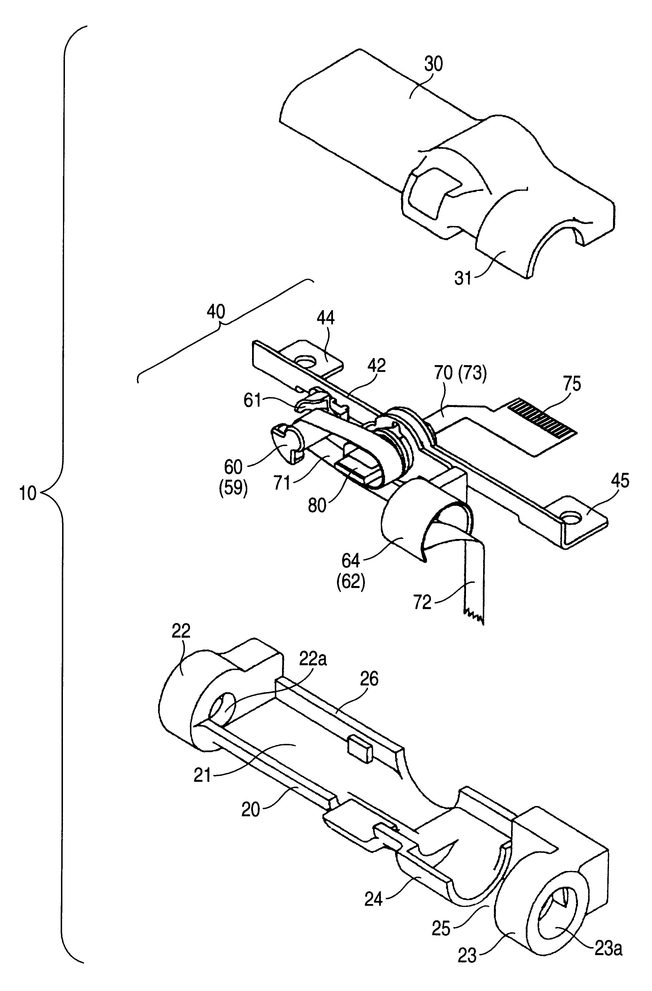
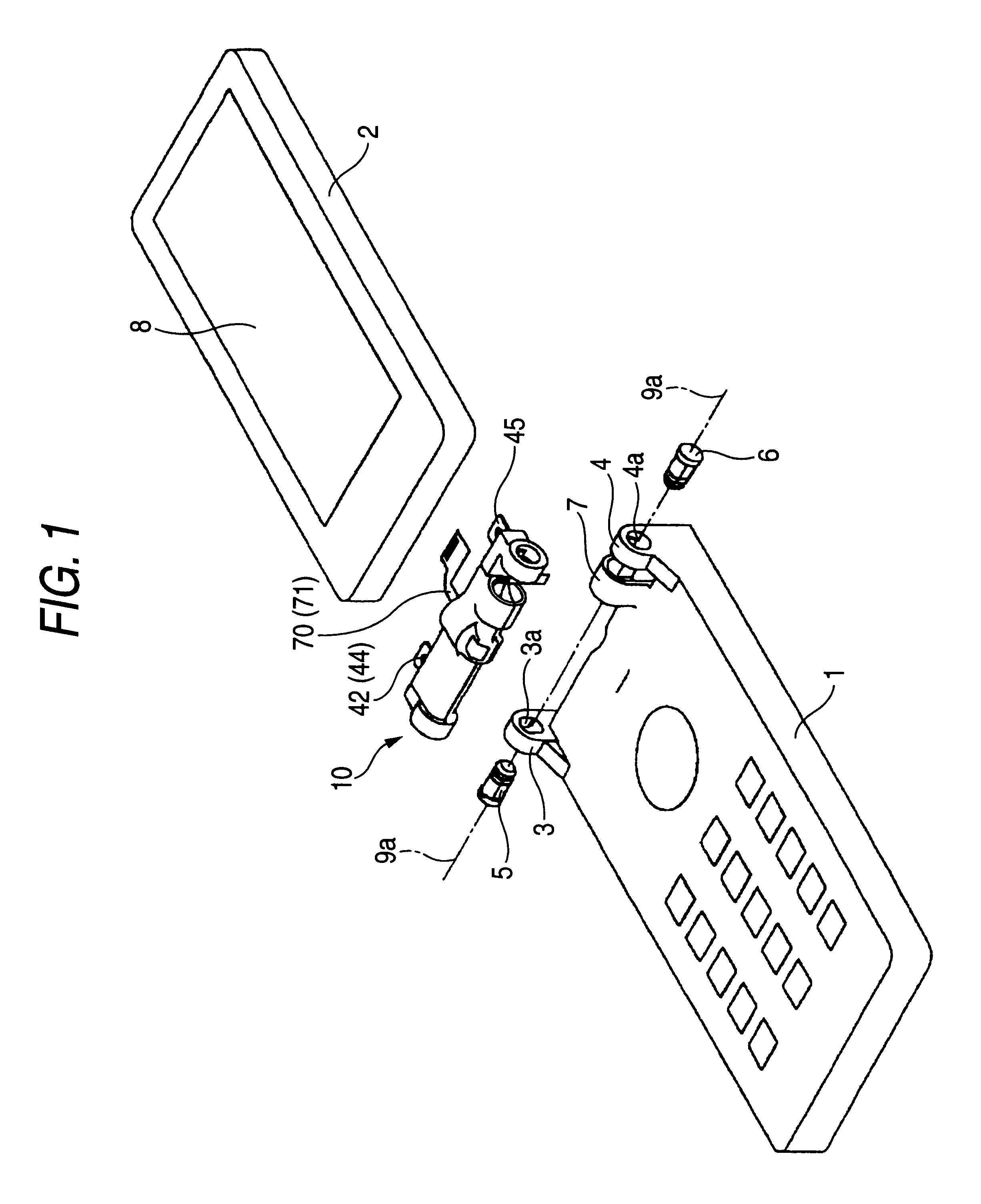
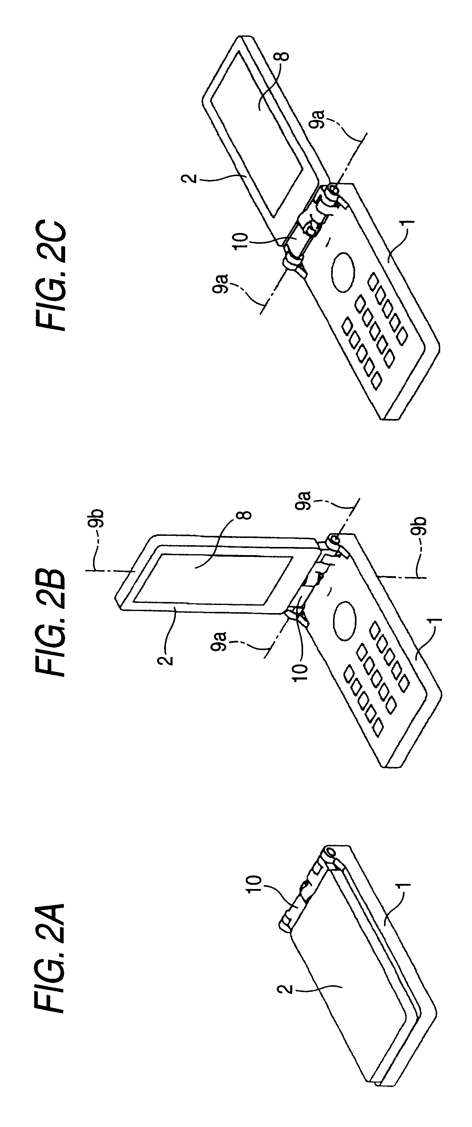
This embodiment is directed to a case in which a rotary structure for relaying signals is applied to a portable cellular phone, wherein a manipulation module 1 and a display module 2 are rotatably mounted about two axes 9a, 9b which are orthogonal to each other by way of a support body 10.

With respect to the manipulation module 1, as shown in FIG. 1, a pair of ribs 3, 4 which are served for mounting the display module 2 are fixed to both ends of a peripheral portion of one surface thereof in a protruding manner. Particularly, in the vicinity of an inner side of the rib 4, a concealing portion 7 having an approximately U shaped cross section is integrally formed with one surface of the manipulation module 1.

As shown in FIG. 1, a liquid crystal panel 8 which is connected to a large number of signal lines is mounted on one surface of the display module 2. The display mod...


PUM


Abstract

The present invention provides a space-saving rotary structure for relaying signals which can relay a large number of signal lines without causing a disconnection of the signal lines. The rotary structure for relaying signals comprising a fixed frame which is supported and fixed in the inside of first and second casings, a rotary sleeve which is rotatably inserted into a through hole of the fixed frame and has a distal end thereof projected to the outside of the first and the second casing, a rotary frame which is arranged outside the first and second casings and is fixed to the distal end of the rotary sleeve such that the rotary frame is integrally rotatable with the rotary sleeve, and a flexible printed wiring film which has a distal end thereof pulled out to the outside of the first and second casings along the rotary sleeve and is wound around a winding tongue of the rotary sleeve which is positioned in the inside of the first and the second casings.

Description

1. Field of the InventionThe present invention relates to a rotary structure for relaying signals, for example, a rotary structure for relaying signals which can be rotated such that a display module of a portable cellular phone can be twisted.2. Description of the Related ArtConventionally, as a portable cellular phone, there has been known a portable cellular phone which supports a display module on a manipulation module using a hinge by way of a support body such that the display module can be opened and closed. Particularly, when the portable cellular phone requires a large number of signal lines, to miniaturize the device and to prevent the fatigue disconnection of the signal lines attributed to the repeated operations of the display module, the manipulation module and the display module are electrically connected by way of a flexible printed wiring film for relaying signals.However, with respect to the above-mentioned portable cellular phone, it is impossible to rotate the ope...

Claims


Application Information

Patent Timeline
Patent Type & Authority Patents(United States)
IPC IPC(8): H01R35/00H01R35/04H04M1/02H05K1/00H01R35/02F16C11/10H01R12/50H05K5/02H05K7/14
CPCH01R35/04H04M1/0212H05K1/028H01R35/025H01R12/7076Y10S248/919Y10S248/917H04B1/38H04M1/02
Inventor HEMMI, YOSHINOBUUCHIDA, TSUYOSHITAKAMORI, SATOSHI
Owner ORMON CORP
Why Eureka
Try Eureka